I recently acquired a Roberts 770 r2r and decided to remove the monoblocks and modify them to SE amps with line level input only.
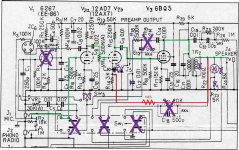
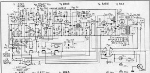
I removed a lot of components that will not be used. The existing line level inputs go to the 12ax7. The existing Feedback loops are not optimal for the standalone amp (I checked frequency response for both). Ideally I want the amp with as little feedback as possible.
I have attached a switch to switch between pentode and triode. Using NFB resistor I can get the response to be flat but I think the 2nd stage of the 12ax7 is suffering from miller effect and limiting the HF. I checked all the other stages individually and they are flat. Did test with no NFB and with a cathode bypass on the second half of the 12ax7, decreasing HF.
Is there anything that can be done with the Miller effect?
I do see a few other options:
1. Reconfiguring the EF86 as the input and driver.
2. Converting the second half of the 12ax7 to a cathode follower
3. connect the line input directly to the volume pot before the 2nd half of the 12ax7.
Should I be able to run the amp in triode mode without any NFB? And then use some NFB when pentode connected.
Suggestions are appreciated. Any of the options better than the others?
BTW, the amp sounds very good with the NFB. Very silent.
Alfredo
Attachments
Last edited:
Moderator, I think there is a problem with the thread as I received a notification via email of a posting made by Costis. Where did it go? I copied and pasted from the email to include the response.
Costis, thanks for the very good info.
I think the power supply regulation is not to bad, I attached the diagram that includes the psu. It uses a 6H choke. I don't hear any hum at all. Also, DC gets injected into the filament to raise it above ground.
I think the transformer is not bad, when I checked the open loop response it is flat. I did this by comparing the response coming into the transformer primary vs the secondary into a 8 ohm load.
If I return C15 ground to the secondary, wouldn't I need to move the cathode resistor to it as well (R17).
How about swapping the 12ax7 with something else?
Thanks
Well...
As you guessed correctly, a 12AX7 has more than enough gain to drive a 6BQ5. So Option no 2 is the best.
Yes, you should be able to run the amp in triode mode without any NFB, provided that you improve the filtering of the power supply. (I am guessing, because you did not attach the schematic of the PSU.). Expect 2 Watts at mos from triode mode.
The issue is the output transformer. I see it has a lot of compensation networks around it which could mean it is not of good quality, and these were need it to bring it in line to work good enough under feedback.
So if you remove all these, (C11 too), you can introduce a little feedback by returning C15 ground to one side of the transformer secondary.
All this si OK (maybe) for triode mode, but for pentode, you ll have to use global feedback like you have marked on the red line. It is bettter if you have a scope to check for ringing , adjusting compensation networks etc.
If you do not, better run it as triode, with the short and failproof feedback as above.
Costis, thanks for the very good info.
I think the power supply regulation is not to bad, I attached the diagram that includes the psu. It uses a 6H choke. I don't hear any hum at all. Also, DC gets injected into the filament to raise it above ground.
I think the transformer is not bad, when I checked the open loop response it is flat. I did this by comparing the response coming into the transformer primary vs the secondary into a 8 ohm load.
If I return C15 ground to the secondary, wouldn't I need to move the cathode resistor to it as well (R17).
How about swapping the 12ax7 with something else?
Thanks
Attachments
The subject is well covered, probably leading to few responses:
http://www.diyaudio.com/forums/analogue-source/158856-akai-m-8-amplifiers.html
http://www.diyaudio.com/forums/tubes-valves/166512-akai-m8-rebuild-up-running.html
http://www.diyaudio.com/forums/swap-meet/160321-akai-m-8-tube-amplifiers.html
http://www.diyaudio.com/forums/tubes-valves/158330-akai-m8-rebuild-restore-will-work.html
http://www.diyaudio.com/forums/tubes-valves/161960-troubleshooting-12b4-rh84-akai-project.html
A number of ways to make these into very nice little amps.
dave
Oops , I thought my connection got stuck when I posted.
Anyway, looks like a nice power supply too. maybe you ll want to up C25 to 47 or 100uF. Or, if they re both old electrolytics, change them. Dont fit a higher value cap in C26, stay with 22uF.
The cathode resistor , even if you move the cathode cap, stays where it is, we don't want to saturate the secondary with DC current")
As for the 12ax7, no reason whatsoever to change it, at least make it work like that, this is for later tinkering.
My conclusion: 12ax7 gain stage, 12ax7 cathode follower, short feedback loop if you go triode, or add the longer feedback loop, too, if you go if you go pentode.
Change all electrolytics, all paper-in-wax ones too, and any resistors that have drifted in value.
O-O
Anyway, looks like a nice power supply too. maybe you ll want to up C25 to 47 or 100uF. Or, if they re both old electrolytics, change them. Dont fit a higher value cap in C26, stay with 22uF.
The cathode resistor , even if you move the cathode cap, stays where it is, we don't want to saturate the secondary with DC current
As for the 12ax7, no reason whatsoever to change it, at least make it work like that, this is for later tinkering.
My conclusion: 12ax7 gain stage, 12ax7 cathode follower, short feedback loop if you go triode, or add the longer feedback loop, too, if you go if you go pentode.
Change all electrolytics, all paper-in-wax ones too, and any resistors that have drifted in value.
O-O
I remember those tape machines. I was amazed at the quality of the playback.
Properly configured, the amplifiers should perform very well. The output transformers have a wide response.
Back in the day, they were considered "the poor man's Ampex" and were used by many radio stations.
Properly configured, the amplifiers should perform very well. The output transformers have a wide response.
Back in the day, they were considered "the poor man's Ampex" and were used by many radio stations.
Thanks Dave,The subject is well covered, probably leading to few responses:
http://www.diyaudio.com/forums/analogue-source/158856-akai-m-8-amplifiers.html
http://www.diyaudio.com/forums/tubes-valves/166512-akai-m8-rebuild-up-running.html
http://www.diyaudio.com/forums/swap-meet/160321-akai-m-8-tube-amplifiers.html
http://www.diyaudio.com/forums/tubes-valves/158330-akai-m8-rebuild-restore-will-work.html
http://www.diyaudio.com/forums/tubes-valves/161960-troubleshooting-12b4-rh84-akai-project.html
A number of ways to make these into very nice little amps.
dave
I have read all of them, some are overhauling by recapping, others are a complete reuse of the components and some are mods to use as preamps, keeping the pentode amp circuitry pretty much intact.
I want to optimize it with what is already there. I believe the original pentode circuitry was optimized for the playback from tape and the recording to it, it was not meant as a simple line in se amp.
@costis
I already did a quick test on what could be the cathode follower output and the response is very flat. I have not changed the CF cathode resistor so the swing is very low. What is best here? Divide the load of the follower in two or put the whole thing in the cathode?
Oops , I thought my connection got stuck when I posted.
My conclusion: 12ax7 gain stage, 12ax7 cathode follower, short feedback loop if you go triode, or add the longer feedback loop, too, if you go if you go pentode.
O-O
I am planning to use a triode switch and a NFB switch. The longer feedback loop, also to the cathode of the CF?
I'll agree that the electronics were very good. But the transport was terrible. Because there were no pressure pads against the heads, intimate tape contact with the heads was accomplished with hold-back tension in the supply reel. With only one motor, a supply clutch was used. A thin felt washer sandwiched between two pieces of plastic was a cheap and dirty design that failed to work properly over time. As the plastic surfaces became polished from slippage, cogging would occur causing flutter. The fix was to rough up the surfaces with sandpaper and reassemble only to have the cogging return again soon after.I remember those tape machines. I was amazed at the quality of the playback.
Moderator, I think there is a problem with the thread as I received a notification via email of a posting made by Costis. Where did it go? I copied and pasted from the email to include the response.
<snip>
 No forum problem, Costis just deleted his post. If Costis agrees I can reinstate.
It's OK, I deleted iy by mistake, sorry
I already did a quick test on what could be the cathode follower output and the response is very flat. I have not changed the CF cathode resistor so the swing is very low. What is best here? Divide the load of the follower in two or put the whole thing in the cathode?
Try connecting the cathode follower properly, i.e. anode ath HV+,cathode load 100K and biasinf resistor 1.5 Kohm
I am planning to use a triode switch and a NFB switch. The longer feedback loop, also to the cathode of the CF?
Build it one at a time, then decide which one you like best
I'll agree that the electronics were very good. But the transport was terrible. Because there were no pressure pads against the heads, intimate tape contact with the heads was accomplished with hold-back tension in the supply reel. With only one motor, a supply clutch was used. A thin felt washer sandwiched between two pieces of plastic was a cheap and dirty design that failed to work properly over time. As the plastic surfaces became polished from slippage, cogging would occur causing flutter. The fix was to rough up the surfaces with sandpaper and reassemble only to have the cogging return again soon after.
Thanks for the memory jog. I had forgotten about the felt washer. I do remember replacing the entire supply assembly on more than one occasion.
Sanding the plastic didn't work too well.
- Status
- This old topic is closed. If you want to reopen this topic, contact a moderator using the "Report Post" button.
- Home
- Amplifiers
- Tubes / Valves
- Need help in modifying Roberts 770 monoblocks