Hi everybody,
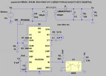
I'm trying to design a 12v to 24v(&24A) flyback SMPS for a low impedance class D audio amplifier.
First of all I want to simulate on it LTSpice to be sure that is well designed, but I've found some problems. I don't know if the SMPS its bad designed or bad simulated.
Everything works perfectly except the power consumption, I think that the problem is at the transformer model because the magnetization inductance sink 180A from the battery .
.
If anyone knows about this please tell me, I don't know what to do.
P.D.: This is my first post at this forum, be patient with me please .
I'm trying to design a 12v to 24v(&24A) flyback SMPS for a low impedance class D audio amplifier.
First of all I want to simulate on it LTSpice to be sure that is well designed, but I've found some problems. I don't know if the SMPS its bad designed or bad simulated.
Everything works perfectly except the power consumption, I think that the problem is at the transformer model because the magnetization inductance sink 180A from the battery
.If anyone knows about this please tell me, I don't know what to do.
P.D.: This is my first post at this forum, be patient with me please
.Attachments
Good Morning
The sg3525 data sheet says the absolute maximum output is 500mA
this would only drive the FET gate to 5V (if it did even that) because of the 10R to ground.
Rather than drive a single FET with both outputs through diodes, use two FET's each with its own drive (A & B), put the 10R in series with each gate line and you can still use a single inductor. You will not need a resistor to ground on the gate lines.
Since this is a flyback design and has a common ground, there is not really a need for a second winding on the transformer. Connect the output diode directly to the FET drain/inductor line.
I'm not sure of the purpose of Lm...is it just for LTSpice?
The feedback section of R1/U1 seems to be operating in a "linear" fashion with the threshold of the SG setting the regulation point. If you added a Zener diode in place of part of R1 the regulation point would be more well defined.
I was told at a SMPS seminar many years ago that a problem had occurred with a flyback design using Schottky diodes alone. The problem was that they don't conduct for a very small fraction of a second and this allowed the flyback spike to destroy the switching FET due to drain voltage ratings. I am not sure this is true but there seems to be snubbers or flyback clamps on FET drain lines in a lot of designs. The solution that was presented at that time was to place an ultrafast diode in parallel with the Schottky diode.
100uH might be a little high in value for power you are trying to put through it. If the inductor value is too high, the current will not rise to a very large amount in the time allowed and the energy stored ( I^2 * L ) won't be very high. This I^2 * L stored energy , multiplied by the pulse rate (switching frequency) results on your power output. If the inductor value is too low then the duty cycle that the regulator will adjust to get your power output will be low. It will work but the FET switching times will be a higher % of the overall "on time" and this will result in lower efficiency and a warmer FET, raising Rds ON values for the FET...additionally lowering efficiency further.
MAXIM IC had some good ap notes for inductor calculations. Other companies will also have good ap noted.
have fun
Hi Dug,
thanks a lot for your answer.
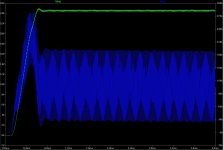
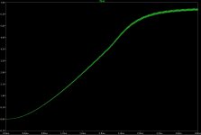
resolving your question, the Lm is the magnetization inductance of the ideal model of a transformer, the problem is that if I delete it the voltage won't rise to 24V (you can see it at the new image), why is happening this?.
Apart of that, wich will be the best inductance for the primary?
thanks a lot for your answer.
resolving your question, the Lm is the magnetization inductance of the ideal model of a transformer, the problem is that if I delete it the voltage won't rise to 24V (you can see it at the new image), why is happening this?.
Apart of that, wich will be the best inductance for the primary?
Attachments
There is no such thing as magnetizing inductance part of a flyback transformer. The whole inductance is magnetizing inductance and how it works is 2 coupled inductors rather than a typical transformer, that is primary and secondary currents flow in different moments and the energy is being stored and released in the magnetic field each cycle.
The feedback loop doesn't look very robust, it seems to rely on the opto's CTR completely and SG's error amp is just a follower.... try decreasing R1 and put a 20V zener in series.
Last not least why flyback and not push-pull?
The feedback loop doesn't look very robust, it seems to rely on the opto's CTR completely and SG's error amp is just a follower.... try decreasing R1 and put a 20V zener in series.
Last not least why flyback and not push-pull?
After I posted, I remembered another function of the SG chip.
each output will have a maximum duty cycle of less than 50% since it is designed for push-pull output transformers.
The duty cycle limit is to allow the stored energy in the core time to get dumped into the load/filter.
If you are running one FET or even one core, there will be no time for this.
You should use two FET's (each its own 10R series in the gate cct) and two cores and of course two rectifiers
Then each core has time to dump its energy
Hi everybody again,
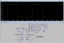
I changed the topology to a push-pull converter like you suggested. Everything it's working perfectly, but the current through the transformer (L1 & L2) continues working wrong (see it at the image).
I don't know why the current through L1 is greater than L2, what I'm doing wrong? The resistance in serie of both is 0.02 ohm.
Thanks.
Attachments
DC-DC Converter Design
As mentioned earlier, I wouldn't worry too much about primary inductance. Inductance only becomes a big issue at much higher switching frequencies. Below 75KHz (where many high-power SMPS's run at) you should be fine. Therefor, I think you'd be fine up to 12 or so primary windings which will allow you to have a better window of regulation for your secondary winding's count.
Questions:
What frequency are you planning (and modeling) to run?
How tight do you need the secondary regulation?
What core material are you going to run?
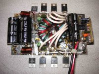
Attached is a picture of a 500W DC/DC converter I designed and built. The core is a Ferroxcube 3C81 material running at ~23KHz. I use an SG3526 PWM IC and a dual FET driver. It converts 12V to +/- 40 for a car amplifier. I was able to get close to 800W from it, but that's beyond the continuous ratings of the secondary rectifiers, so it was only briefly. It's un-regulated, only relying on the transformer ratio of 4:12 (3:1 technically), but is surprisingly stable under varying load. That is, as long as the input voltage is stable. Of course, that also means as the input swings from 12 to 14.4VDC, the secondary fluctuates from +/-35 to +/-42 depending on load. Building it this was makes it's design very simple with almost no part being critical and it works great for a car audio amp.
I'm posting my design as an example because you can meet all of your needs with a similar design. I can draw up a schematic if you'd like to see the specifics. I hope this helps.
As mentioned earlier, I wouldn't worry too much about primary inductance. Inductance only becomes a big issue at much higher switching frequencies. Below 75KHz (where many high-power SMPS's run at) you should be fine. Therefor, I think you'd be fine up to 12 or so primary windings which will allow you to have a better window of regulation for your secondary winding's count.
Questions:
What frequency are you planning (and modeling) to run?
How tight do you need the secondary regulation?
What core material are you going to run?
Attached is a picture of a 500W DC/DC converter I designed and built. The core is a Ferroxcube 3C81 material running at ~23KHz. I use an SG3526 PWM IC and a dual FET driver. It converts 12V to +/- 40 for a car amplifier. I was able to get close to 800W from it, but that's beyond the continuous ratings of the secondary rectifiers, so it was only briefly. It's un-regulated, only relying on the transformer ratio of 4:12 (3:1 technically), but is surprisingly stable under varying load. That is, as long as the input voltage is stable. Of course, that also means as the input swings from 12 to 14.4VDC, the secondary fluctuates from +/-35 to +/-42 depending on load. Building it this was makes it's design very simple with almost no part being critical and it works great for a car audio amp.
I'm posting my design as an example because you can meet all of your needs with a similar design. I can draw up a schematic if you'd like to see the specifics. I hope this helps.
Attachments
Wow! thanks you so much DCPreamp!
Answering your question, I'm using 50kHz switching frequency and for the output regulation I will use a opto (I didn't do it yet). I'm simulating it at LTspice to check that is working perfectly.
My principal problem is at the transformer, I don't know anything about the core material, cable thikness, primary and secundary inductances, series resistances, etc. So I'm a little bit scared about making the transformer by myself.
For wire, pretty basic magnet wire, Litz wire (multi-strand wire), enameled wire, etc. will all do. It can be purchased from eBay, Digi-Key, Newerk, etc. Do some research on AWG of the wire, how paralleling strands handles more current, etc.
Next, for switching transformer cores, do some further research on their properties, losses, etc. But make sure to look at this guy: eBay My World - audiosector because he sells a number of different cores ideal for high-power switching transformers. For under $15 (if you're in the USA) you'll have a core good for 1KW. Like this one: 170799584797 (go to eBay and paste this number into a search box).
You still have some work to do, but that should eliminate a lot of it. Once you have the core & wire, actually wrapping the transformer is easy. Plus, a lot of the cores are pretty forgiving from 20 to 100KHz with the primary inductance only being a concern during simulation.
I suggest winding your own over ETD44 or ETD49. You have to calculate the primary turns count basing and f and B, 0.15T at 100kHz or 0.2T at 50kHz are typical values.
Thickness- that's an easy one- choose the thickest that will fit into the winding window based on the bobbin and core dimensions, preferably several thinner wires in parallel.
Thickness- that's an easy one- choose the thickest that will fit into the winding window based on the bobbin and core dimensions, preferably several thinner wires in parallel.
You'll have to make your transformer. It's highly unlikely you'll find an off-the-shelf piece that will meet all your requirements, and even of you did, there would be huge expense in minimum orders.
Where are you located? You can get everything easily in the USA, and pretty easy in most of Europe. Other, more distant locations, may be a problem.
But, again with the vendors I listed, plus some basic epoxy resin, you can wind your own custom, high-performance, switching transformer for under $40 (US). Don't get scared off by this proposal. Seriously, it's easy to do. a 2"/51mm toroid core, or an ETD39, ETD44, or ETD49 in a 3F3, 3C81, 3C85, N87, TSF7070 materials etc. will all work. Based on the winding ratios discussed earlier, wrap the windings on the core (look at my SMPS for an idea & Google for pics of transformers) counting the turns. The wire coating will prevent it from shorting when close together or overlapped. Once completed and verified, apply epoxy resin to keep the windings in place and to prevent them from getting worn because of vibration. Lastly, to solder to the magnet wire, you will need to use a blade to scrape the coating off the wire exposing copper.
You could also, if you live in some obscure corner of the world, or are totally broke, and with enough time, effort, and tenacity, tear apart a large PC power supply, remove the switching power transformer, and modify it for your needs. This is a lot of work, but is also a good learning experience on the proper ways to build transformers. You'd need a supply that meets your needs - a 650 to 1KW rating - and gut it. You'd probably need a couple of them because the likelihood of successfully unwinding a SMPS transformer without damaging it is slim. Check on this forum for how to reuse a transformer.
That's it! Really, only fear and doubt will stop you from building your supply!
Ok, I'll try it whe I finish the design, thank you so much.
Now I'm triying to feedback, I'm doing something like the schematic of page 27 of this paper http://www.datasheetcatalog.org/datasheet/SGSThomsonMicroelectronics/mXywysu.pdf but I don't have great results.
Now I'm triying to feedback, I'm doing something like the schematic of page 27 of this paper http://www.datasheetcatalog.org/datasheet/SGSThomsonMicroelectronics/mXywysu.pdf but I don't have great results.
- Status
- This old topic is closed. If you want to reopen this topic, contact a moderator using the "Report Post" button.
- Home
- Amplifiers
- Power Supplies
- 576W SMPS for car audio amplifier