Good day,
I've built an Avondale NCC200 derivative and have been using it on and off for the last while.
My issue is that the amp picks up a hum once I connect the RCA cables. It does not matter whether the RCA's are connected to the pre-amp or not. Once connected it gets slightly louder but remains at that level irrespective of the volume I'm playing at.
Its bad enough to hear the hum in the background when listening to piano music where there's lots of quieter passages, hence detracting from the whole experience. When player music louder, there's no problem. On less efficient speakers it's not a problem, but on my ZRTs (which is not exactly efficient) I simply can't live with it.
I've tried the following without success:
> Different RCA cables. I've tried some reasonably good ones and a couple of the ones you get with a cheap DVD player. The problem remains the same.
> Shorten both the RCA and signal lines to the shortest practical length.
> Change the signal line from a twisted pair CAT5 wire to a shielded wire. No change and I reverted to the CAT5 wires as they're lighter.
> Unplug the ground wire from star ground.
> Swop live and neutral on transformer input.
> Set-up the 2 PSU's in a manner where the phases are apposed. Basically have the one +/- and the other -/+.
>Inserted a 8R2 resistor between the PSU ground and star. This made things considerably worse.
I found a thread on this forum from 2005 where there appears to be good advice, but since the pictures are no longer available it is difficult to follow. In that case the problem was sorted out by using a *special* RCA cable. Which in my view is not a good solution as the amp still does not behave as one would expect with regular cables.
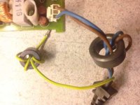
A picture of my grounding scheme:
My apologies if this is old hat - and for the fact that I'm not yet familiar with the forum software.
You help is much appreciated!
Attie
I've built an Avondale NCC200 derivative and have been using it on and off for the last while.
My issue is that the amp picks up a hum once I connect the RCA cables. It does not matter whether the RCA's are connected to the pre-amp or not. Once connected it gets slightly louder but remains at that level irrespective of the volume I'm playing at.
Its bad enough to hear the hum in the background when listening to piano music where there's lots of quieter passages, hence detracting from the whole experience. When player music louder, there's no problem. On less efficient speakers it's not a problem, but on my ZRTs (which is not exactly efficient) I simply can't live with it.
I've tried the following without success:
> Different RCA cables. I've tried some reasonably good ones and a couple of the ones you get with a cheap DVD player. The problem remains the same.
> Shorten both the RCA and signal lines to the shortest practical length.
> Change the signal line from a twisted pair CAT5 wire to a shielded wire. No change and I reverted to the CAT5 wires as they're lighter.
> Unplug the ground wire from star ground.
> Swop live and neutral on transformer input.
> Set-up the 2 PSU's in a manner where the phases are apposed. Basically have the one +/- and the other -/+.
>Inserted a 8R2 resistor between the PSU ground and star. This made things considerably worse.
I found a thread on this forum from 2005 where there appears to be good advice, but since the pictures are no longer available it is difficult to follow. In that case the problem was sorted out by using a *special* RCA cable. Which in my view is not a good solution as the amp still does not behave as one would expect with regular cables.
A picture of my grounding scheme:
An externally hosted image should be here but it was not working when we last tested it.
My apologies if this is old hat - and for the fact that I'm not yet familiar with the forum software.
You help is much appreciated!
Attie
NCC200 clone
You don't give details of what you have physically built or how you have wired it to the power supplies, mains earth, chassis connection,
star ground etc. These are critical arrangements that must be correctly set out and connected to prevent hum and hum loops in amplifiers.
If you simply copied the NCC200 schematic, it's understandable how you might have missed the necessary details but perhaps there are other
wiring or shielding matters that need attention too. Can you post a pic of your assembly so others can look to spot the problems, if any?
I think you may need to try posting the diagram again too.
Meantime, you could search the subject "Star grounding" on the forum or Wikipaedia etc. and look at the wiring arrangements in the many Pics
of the similar "NAP140 kit on Ebay" thread.
Last edited:
Thanks for your reply Ian. I tried attaching a picture of the grounding arrangement in my first post but it appears I need more practice.....
I built 2 amp boards and 2 PSU boards, which includes the speaker protect circuit. Both PSU's are supplied from a single 250VA 33-0-33 transformer.
I did not copy the boards - it was a group buy type thing on a local SA forum, put together by one of the local guys. I've asked for advice there as well - which I listed in my first post.
PSU boards are located directly below the amp boards.
RCA connectors are isolated from the chassis.
>There is a single star ground point for everything on the chassis
> PSU grounds to star (in the attached pic black)
> Amp ground goes to PSU ground
> Transformer center tap to star (black)
> Power outlet ground to star (white)
I try again to post pics of the above:
An externally hosted image should be here but it was not working when we last tested it.
An externally hosted image should be here but it was not working when we last tested it.
An externally hosted image should be here but it was not working when we last tested it.
Last edited:
A couple of other details:
1) You are using 33V AC supplies so I guess you measure about 47V rails. That's no problem for MJ15003/4 outputs,
but I assume all the other components are up-rated to suit the higher than 40V rails. Those semis in Avondale's design
would mostly be on their maximum unloaded limits here.
2) The position you place the amplifiers, directly above the PSUs is not so good from the POV of EMR going straight to
the inputs. It may be a greater distance than it appears to me but I would try to increase the distance between the
rectifiers, PSU wiring and the amplifiers and signal leads as much as possible to minimise 100Hz hum.
3)The ~3mm aluminium heatsink bracket is rather thin for a 200W transistor and they are positioned on the far edge.
You will have to derate the usage or overheating of the case is certain at that supply voltage.
------------------------------------------------
The transformer grounding is not obvious, I think you say you have made chassis earth the star earth and this is
not correct. Star earth is at the PSU common and a strap leads to chassis earth from there, otherwise you introduce
lead resistance into the earth path. Obviously, the resistance between each PSU star ground must be as close to zero
as possible and the benefits of separate supplies vanish without separate windings to permit isolated supplies.
Normally, star ground is above chassis earth but then strapped to it at one point, which may be safety/chassis earth
or another chassis point, according to safety rules which are endlessly changing to satisfy bureaucratic whims.
Safety/chassis earth accepts mains earth, transformer frame earth and a single lead from PSU star ground.
this connection may even be made at another chassis point, depending on power authority rules.
Perhaps this isn't the case but I would hope the transformer secondary common or CT is returned direct to PSU or rather star
ground. If there is a transformer frame or shield strap connection, by all means connect this to chassis/safety earth.
Safety rules may insist on this anyway.
I hope that the problem is just that simple and you get some improvement
if I have understood you correctly. Let's hear what you and others may have to say on it
Suggestion ....
Give the safety ground its own chassis connection about an inch away and secure it with a locking nut/washer so you dont keep disturbing it . Then check it has a good electrical connection to the chassis with a meter.
Connect all amp and psu grounds directly to the star ground , including the loudspeaker output returns . Make the psu grounds as short as possible .
Last edited:
A couple of other details:
1) You are using 33V AC supplies so I guess you measure about 47V rails. That's no problem for MJ15003/4 outputs,
but I assume all the other components are up-rated to suit the higher than 40V rails. Those semis in Avondale's design
would mostly be on their maximum unloaded limits here.
2) The position you place the amplifiers, directly above the PSUs is not so good from the POV of EMR going straight to
the inputs. It may be a greater distance than it appears to me but I would try to increase the distance between the
rectifiers, PSU wiring and the amplifiers and signal leads as much as possible to minimise 100Hz hum.
3)The ~3mm aluminium heatsink bracket is rather thin for a 200W transistor and they are positioned on the far edge.
You will have to derate the usage or overheating of the case is certain at that supply voltage.
------------------------------------------------
The transformer grounding is not obvious, I think you say you have made chassis earth the star earth and this is
not correct. Star earth is at the PSU common and a strap leads to chassis earth from there, otherwise you introduce
lead resistance into the earth path. Obviously, the resistance between each PSU star ground must be as close to zero
as possible and the benefits of separate supplies vanish without separate windings to permit isolated supplies.
Normally, star ground is above chassis earth but then strapped to it at one point, which may be safety/chassis earth
or another chassis point, according to safety rules which are endlessly changing to satisfy bureaucratic whims.
Safety/chassis earth accepts mains earth, transformer frame earth and a single lead from PSU star ground.
this connection may even be made at another chassis point, depending on power authority rules.
Perhaps this isn't the case but I would hope the transformer secondary common or CT is returned direct to PSU or rather star
ground. If there is a transformer frame or shield strap connection, by all means connect this to chassis/safety earth.
Safety rules may insist on this anyway.
I hope that the problem is just that simple and you get some improvement
if I have understood you correctly. Let's hear what you and others may have to say on it
There's actually a few of these I can address now:
1) The lowest rated component is 63V, so I should be safe on the voltage margin.
2) Which PSU component would emit the most EMR? The amp board is not very far (3cm max I think) from the PSU caps. The rest of the components are about 5cm from the amp board though. I'll make a plan to tidy up my wiring and see if I can keep them further away from the amp board.
3) I had a bit of difficulty sourcing a small piece of alu angle of a reasonable thickness and was also a bit worried about that. However, this weekend I pushed the amp a bit - ran it for an entire CD's duration with the volume on about 2 o'clock. My normal listening volume is 9-10 o'clock. The heat sinks got the warmest yet, but I don't think more than 40 deg C. The back panel and alu angle was just about the same temperature. But you're right - that's another thing I should look at bullet proofing.
-----------
The next bit of of your comment I'll study a bit and see if I can figure out what needs to be done.
BTW, the transformer was meant just to get me going. The 'pie in the sky' plan is to get dual toroidals.
I know this is a bit of a contentious issue, but what VA rating would you consider 'good' for my purpose? The amp is meant to deliver around 90W/c into 8 Ohms. I was thinking 220-300VA / channel, but then an engineer, who builds amps, mentioned he's using 110VA for 80W/c with very little electrical evidence for problems when straining the amp.
+1 to Epicyclic
but i think you will have to move the mains socket and wiring!
Shorten that white earth wire. but first try a ferrite on it!
Shorten all mains wiring too, cant see from the pics where its routed, but keep it at least 2cm away from all other wiring.
Rotate the transformer orientation slowly while listening for hum
also try grounding the RCA sockets, disconnecting the signal ground wires from sockets.
Last edited:
Hi Atjan
You raise a lot more issues than one reply can hope to handle but let's see:
1) The rating is more of a concern for the semis, where simply looking at Vceo max. etc and thinking "it is within"
is not right. The matter is Safe Operating Area and that takes into account the current increase that also occurs
when you raise voltage. There are charts in the data sheets to determine what safe limits apply to components.
2)Every part that carries diode switching current emits noise. The mere presence of lead resistance forms a transmitter
of EMR. That means the PSU transformer leads, rail leads, diode bodies, cap leads and of course, the traces on the PCB.
If you have spare cash, you can buy a cheap detector of low frequency EM fields or fit a solenoid coil to your AC DMM
terminals and watch it go berserk as you approach the PSU when it is delivering high current. The best insurance
is short leads, twisted together as pairs of opposite polarity for field cancellation and routed as far distant as possible
from low signal and feedback paths - anywhere.
However, this is not likely the main issue here - whilst you have earthing issues.
3)The low temp. you measure on the sink likely reflects how poorly it removes heat from the transistor, not the other
way around. If you sense the temp. under these conditions, on the top of the case, you might be surprised how much
higher it is than it ought to be on an efficient sink. I guess you are like us, coming into winter so all is fine but in
summer, you may not be so happy.
............................................................................................................................................................
further to (2)
The galling part about class AB amplifiers is that there is no hum or noise until the signal causes it to rise with
output power. It only becomes evident as a part of the signal, colouring the audio. If the amplifier is biased into class A
(don't try with this design) you will soon hear what is added to the audio at high power.
As transformers go, there is nothing wrong with underrating transformers like many UK manufacturers continue to do.
The assumption is that that users don't push their equipment to continuous maximum rated output in both channels
because stereo programme doesn't require it, but the rails do sag at high power and form an effective and economical
protection - something DIY guys blithely eschew. I think a stiff or high current supply is a guarantee of equally stiff
failures when accidents occur - and if there is enough current to weld your relay contacts, they surely will.
Thanks agian everyone for your interest and advice.
>The mains is routed from the middle of the back panel along the bottom corner to just behind the front panel where the switch is. From the switch, along the front bottom corner to the transformer. I don't think I've much options in that regard.
> All the AC carrying wires are twisted.
>I've done the transformer rotation - no change. I've also had it on its side, etc.
> The RCA's are currently isolated from the back panel. If you say ground them, please explain?
> Sorry - novice - could you explain the 'ferite' on the mains earth? Resistor?
+1 to Epicyclic
but i think you will have to move the mains socket and wiring!
Shorten that white earth wire. but first try a ferrite on it!
Shorten all mains wiring too, cant see from the pics where its routed, but keep it at least 2cm away from all other wiring.
Rotate the transformer orientation slowly while listening for hum
also try grounding the RCA sockets, disconnecting the signal ground wires from sockets.
>The mains is routed from the middle of the back panel along the bottom corner to just behind the front panel where the switch is. From the switch, along the front bottom corner to the transformer. I don't think I've much options in that regard.
> All the AC carrying wires are twisted.
>I've done the transformer rotation - no change. I've also had it on its side, etc.
> The RCA's are currently isolated from the back panel. If you say ground them, please explain?
> Sorry - novice - could you explain the 'ferite' on the mains earth? Resistor?
I cannot see any kind of heatsink other than the flimsty steel back panel.
There's an alu heat sink behind it. I'd rather not upset any stomachs by going into any kind of details on that....
Suffice to say there's one and it works reasonably well.As previous, there are small gains to be made reducing hum after you get rid of the major problem which is earth or ground wiring.
Follow epicyclic's suggestion, or, for the sake of simplicity and understanding, remove the second PSU and its amplifier from the circuit.
The relay can remain operational if you wish.
Now, connect the transformer CT to the remaining PSU star ground and ensure a chassis ground connection from there.
Assuming you have the other returns to PSU star ground in place, such as the speaker return, input ground and amplifier
power 0V, you should have sweet sound in one channel without hum. You can then parallel the second amplifier onto this
PSU and verify that it also has low hum and you have stereo. If not, you either misunderstand or your wiring is incorrect,
Please post your actual connection schematic.
Yes, but that also happens because you complete the ground circuit - a hum loop. If both source and amp.Just looking back at the first post, the hum only occurs when the rca leads are plugged in..?
have earth connections to mains and the signal ground is connected to both chassis before star ground and
any "ground lift" resistor .........mmmmmmMMMMMMMMM!

With star ground right on the chassis, I think that is the problem. We just have to wait for Atjan to correct it.
Hi,
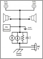
I had a problem like yours that when you connect any external devices the amplifier started to hums. Just like the problem your experiencing. I tried different configuration with no success. So I searched on how to get rid it off and the only way that I was able to cleaned it was wiring the amplifier as shown in the attached diagram. It may not fix your problem but when everything you try failed give it a try. Good luck
I had a problem like yours that when you connect any external devices the amplifier started to hums. Just like the problem your experiencing. I tried different configuration with no success. So I searched on how to get rid it off and the only way that I was able to cleaned it was wiring the amplifier as shown in the attached diagram. It may not fix your problem but when everything you try failed give it a try. Good luck
Attachments
I've finally gotten round to making up the diagram requested muuuch earlier.
Shown is what I tried tonight - with no success:
-Moved the mains earth to another location on the chassis - no change
- I then removed one channel from power and star ground - no change
- I then added a 10 Ohm resistor on the mains earth - no change
- Take output earth to star and then with 10 Ohm resistor in line - no change.
- Packed the freakin thing up and started writing this post. :
Irritatingly, there's only noise when the RCA is connected - even without it being connected to the preamp. If its lying on top of the power cable the hum is pretty awful. If I lift it straight in the air - much less hum.
For the record - all of this was done in my study - which is on a different breaker switch to the lounge where the amp is normally used.
Here's how its connected no, sans resistors.
1) Should the star ground be isolated from the chassis?
2) Should each channel have its own star ground?
3) If so, how to do with the single CT I have?
Thanks again for your patience!
An externally hosted image should be here but it was not working when we last tested it.
That part is normal. What's your input impedance? I can barely make out a 100k to ground, is that it? Some noise pickup is entirely expected with an input cable hanging in the air. You have checked the cable or tried another, haven't you?Irritatingly, there's only noise when the RCA is connected - even without it being connected to the preamp. If its lying on top of the power cable the hum is pretty awful. If I lift it straight in the air - much less hum.
A signal source presents a much lower impedance at the input, typically just hundreds of ohms. Such effects should entirely disappear then. Try a floating or double insulated signal source, like an MP3 player or most any CD player.
The changes you were making had no effect because you weren't dealing with a ground loop.
You'd generally connect signal ground and chassis at the input side by means of a small ceramic capacitor, 1..10 nF typical. (Multiple such connections may exist.) A resistor to star ground also gives shielding at AF.
Do not connect chassis to safety earth (ground) if possible, rather make sure everything mains-carrying is double insulated and clearance on PCBs is sufficient. (Local electrical safety regulations apply.) Otherwise connection of a grounded signal source - like your average PC - may result in an audible ground loop.
PSU wiring
Hi Atjan
Thanks for the diagram. It makes something clear which, as I see it, is still a problem. The point you mark star earth
is still the point of connection for the transformer CT. This is not correct.
Star earth is actually on the PSU power board. - lower right side where multiple connectors shown, are provided for the purpose.
The speaker ground return connector should also be taken directly to that point. Perhaps the PSU traces ensure this.
The only connection from the whole amplifier(s) to the chassis earth should be a single short lead from the PSU star point
to that chassis earth/safety earth.
Remove that speaker ground connection from the amplifier board (top right side) and see if there is any change.
The correct return point is also to star earth (as above and previous posts). It should not be duplicated as shown.
I imagine you have already tried this, but plug the power amp and source into the same outlet/adaptor. If the hum is reduced,
you may well have to break the earth shields to the source but this is extreme and suggests something silly in the supply wiring
- perhaps even a bad earth strap for the house ground connection?
The reply to your question (1) is above but the star ground is not isolated other than by the small resistance of the chassis
lead/connection. Surprisingly, that tiny resistance is critical in hum reduction, being the very reason we keep the earth points
separate or as close as possible as required.
(2 & 3). Ideally, the star earth points should be identical for a stereo pair using a single transformer winding. That is the reason
for suggesting the single supply so there would be no added earth resistance. In order to use separate PSUs, you ideally need
separate windings on the same transformer or separate transformers. In that case you simply duplicate the amplifier, PSU
and connections. The only common connection is again the chassis earth. Both schemes are used in many commercial designs.
I strongly suggest you read the articles pages on Power Supply Wiring Guidelines design at Rod Elliott's ESP siteto confirm.
The reference amplifier design books by Douglas Self, Randy Slone and Bob Cordell also contain important chapters on this subject.
EDIT. I believe we don't advocate that DIYs attempt double insulated wiring practice. It is certainly prohibited in this country.
Last edited:
- Status
- This old topic is closed. If you want to reopen this topic, contact a moderator using the "Report Post" button.
- Home
- Amplifiers
- Solid State
- Hum on Avondale NCC200 derivative amp