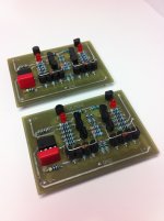
This is a amplifer desined by Kelvin Gilmore in headwize's article. I made it myself last month. It used 2SK170/2SJ74 in place of 2SK389/2SJ109. Sounds very exellent. very comfortable and smooth. more wide more airy. I love it. It's one of the best in my DIY headphone amp collection.^^
Attachments
Where could We see schemes of this devices ?
and here... HeadWize - Project: A Pure Class A Dynamic Headphone Amplifier by Kevin Gilmore
K. Gilmore's electrostatic headphone amp looks great. Are pcb available - bare or stuffed?
I think there are no more pcbs avail from AMB, only two commercial versions fully built.
K. Gilmore's electrostatic headphone amp looks great. Are pcb available - bare or stuffed?
You can find the designer here.
All those paralleled small signal output transistors could have been replaced with just a pair of BD139/140.
And they would sound better IYO?

All those paralleled small signal output transistors could have been replaced with just a pair of BD139/140.
They could...but somehow I don't think it would sound quite as good...
And they would sound better IYO?
I'm surprised this sounds good, or even measures good.
The VAS is wimpy as hell, for example.
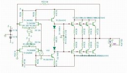
This is the schematic I'm looking at:
http://www.djgardner.com/headphone/gilmore/dynalo/layout/Rev-C/dynalo_rev_c.pdf
Maybe it's the wrong one, I don't know, but it appears that you've merely substituted discrete jfet's for the monolithic original ones.
You can delete R17 and R21, and then replace the load resistors on the two long tail pairs with a current mirror each, no problem.
The collectors of Q3 and Q4 are extremely sensitive to load, so trying to make them drive the bases of 4 transistors is just dumb in my opinion.
The constant current sources for the jfet input differentials is far too complicated. A simple jfet + resistor would have been plenty fine there.
So no, I think this designs sucks.
The basic topology seems to make a lot of sense if you ask me. Some companies have built very fine speaker amps with more "grown-up" versions.I'm surprised this sounds good, or even measures good.
You think so? About 4.4 mA of Ic isn't too bad for a small-signal transistor. That's close to the levels you'd find in a simple speaker amp.The VAS is wimpy as hell, for example.
And end up with an "undefined VAS current" topology. I've simulated ones like that and they seemed to behave reasonably well, but I dunno... an uneasy feeling does remain. One approach I've seen that seemed to make sense was using current mirrors plus (smaller) load resistors. The current mirrors go under the VAS tap then, making VAS Ic well-defined again.You can delete R17 and R21, and then replace the load resistors on the two long tail pairs with a current mirror each, no problem.
The output Qs are high-beta transistors running at considerable Ic (about as much as a TO-92 case will allow, actually). They'd do a fine job at load isolation well down into the double-digit ohms range. With R18/20 there already is considerable loading present in the first place.The collectors of Q3 and Q4 are extremely sensitive to load, so trying to make them drive the bases of 4 transistors is just dumb in my opinion.
I guess capacitive loading at this point forms the dominant pole.
I think the point of the pots was nulling (input stage) distortion. Plus, he gets to attach a DC servo there (for noise reasons?). That one does seem overly fancy when an Evil Electrolytic(R) in the feedback would pretty much have done the same job (it's not like a 100 µF 25V part would be huge or cost a fortune).The constant current sources for the jfet input differentials is far too complicated. A simple jfet + resistor would have been plenty fine there.
Last edited:
I modeled it in Tina, a spice simulator. THD is about 0.01% @ 1khz and 970mV output driving 150ohms. Bandwidth is good. I don't have the exact models for the jfets, so I used general purpose ones. I have good models for the other transistors. I measure about 3.6mA for the VAS transistors, and about 10mA each for the outputs. DC offset is over 100mV, so a servo is needed. I didn't use the servo because they don't reduce distortion. I'm sorry but I am not impressed.
Attachments
K. Gilmore's electrostatic headphone amp looks great. Are pcb available - bare or stuffed?
I believe the KGSS has stopped a while ago but been replaced by a newer version. The kgsshv
KG seems to hang out here-- i'm on a roll... the kgsshv - Do It Yourself - www.Head-Case.org
I got the last of the KGSS pcb's from headamp.
I will make it, sooner or later.
Last edited:
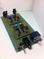
I have finished a Dynalo amplifier with some minor differences, BJT in place of the differential amplifier jFET, and 1N4148 diodes for the current source.
I started with a Spice simulation for two set of available BJT, BC550/BC560 and ksa1015/ksc1815. Both behave well on the computer, so I mounted them with point to point wiring.
Both BJT performed well connected to a sigma22 PSU, and I ordered PCBs. I also ordered a PCB for a more simple PSU with +/-15 VDC output.
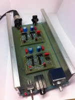
This is the final assembly with E-96 Series resistor (1/4W, 1% and 50ppm), BJT ksa1015 and ksc1815, Gain of 6dB, servo with TL051, current source with 1N4148 diodes and PSU of +/-15.00 VDC
The amplifier measures very well:
Difference between channels of 0.04 dB and flat response, identical in the two channels: -0.03 dB at 20 Hz and 0.00 dB from 80Hz to 20kHz, bandwidth of 2 Hz to 500KHz with + /-3dB.
Less than 1 mV DC offset, after stabilized by the servo
Input impedance greater than 23 kOhm
Output impedance less than 0.75 Ohm
And sounds good too.
I started with a Spice simulation for two set of available BJT, BC550/BC560 and ksa1015/ksc1815. Both behave well on the computer, so I mounted them with point to point wiring.
Both BJT performed well connected to a sigma22 PSU, and I ordered PCBs. I also ordered a PCB for a more simple PSU with +/-15 VDC output.
This is the final assembly with E-96 Series resistor (1/4W, 1% and 50ppm), BJT ksa1015 and ksc1815, Gain of 6dB, servo with TL051, current source with 1N4148 diodes and PSU of +/-15.00 VDC
The amplifier measures very well:
Difference between channels of 0.04 dB and flat response, identical in the two channels: -0.03 dB at 20 Hz and 0.00 dB from 80Hz to 20kHz, bandwidth of 2 Hz to 500KHz with + /-3dB.
Less than 1 mV DC offset, after stabilized by the servo
Input impedance greater than 23 kOhm
Output impedance less than 0.75 Ohm
And sounds good too.
Last edited by a moderator:
All those paralleled small signal output transistors could have been replaced with just a pair of BD139/140.
I don't know whether it was a consideration here, but some designers prefer to parallel small-signal transistors just to obtain a better statistically averaged match between the push and pull sides. Evens out any individual anomalies. But often that's an attempt to get product consistency within loose production and supplier specs.
- Status
- This old topic is closed. If you want to reopen this topic, contact a moderator using the "Report Post" button.
- Home
- Amplifiers
- Headphone Systems
- my gilmore class A amp