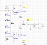
I am building (slowly) a device that will produce a sinusoidal of fixed frequency 200 KHz at 50 V peak, into a load of approximately 15 Ohms. The supply will be a +/- 6V so I have used a transformer to raise the output to the required 50 V.
I am attaching the schematic as I have already built it and tested it.
Under certain conditions it is possible that the load may drop considerably, from 2000 Ohms to anything, even a short. When this happens I want the device to "throttle".
Currently I am feeding the prototype from my bench PSU which automatically employs current limiting, and this protects the device and the load from such conditions.
What can I do to employ some type of similar protection but without using my regulated and current limiting bench PSU?
As a first step I thought of using the voltage that gets developed across R10 and R11 - but I am not sure what to do when this voltage reaches a cerain threshold.
I'd be grateful for any help.
I have designed the output stage to be something like this
Attachments
You need circuitry like this VI Limiters in Amplifiers ......fig 1
It collapses the voltage across the biasing circuit , in your case the 4 diodes , to limit the output current .
It collapses the voltage across the biasing circuit , in your case the 4 diodes , to limit the output current .
Just thinking aloud ")
Efficiency is a major problem. Perhaps reduce those 0.22's.
Is distortion an issue ? Reduce the bias to Class B
Do you need a split supply ?
Use a low value resistor (say 0.01ohm) in the power supply to sense current using an opamp and use that for limiting.
Can use the transformer winding inductance be used to your advantage if it is running at a fixed frequency and you can tune the winding for greater efficiency with cap.
Resistors across B and E for output transistors to stop cross conduction.
You need circuitry like this VI Limiters in Amplifiers ......fig 1
It collapses the voltage across the biasing circuit , in your case the 4 diodes , to limit the output current .
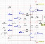
Very good. This "VI" is what I was also trying to do but could not get right. I think I have it now, works on the simulator, will also go build it now. I am not sure I understand the purpose of 82K resistors, I left them out. My new schematic now looks like this.
Attachments
Be aware that this is not a VI limiter, it is only an I limiter.
If you need to protect your devices from exceeding the Safe Operating Area you need a VI limiter.
A VI limiter not only takes the current info but also a sample of the Vce and does the limiting such that the allowed I gets lower with increasing Vce.
An I-only limter does noting, for example, to protect against loads that are inductive or capacitive like many speakers especially with complex xovers.
Edit: Andrew, we xposted....
Edit2: the 82 k resistor referred to above, in fig 1, is essential. It makes it a VI limiter. Don't leave it out.
jan didden
Last edited:
Just thinking aloud
Efficiency is a major problem. Perhaps reduce those 0.22's.
Is distortion an issue ? Reduce the bias to Class B
Do you need a split supply ?
Use a low value resistor (say 0.01ohm) in the power supply to sense current using an opamp and use that for limiting.
Can use the transformer winding inductance be used to your advantage if it is running at a fixed frequency and you can tune the winding for greater efficiency with cap.
Resistors across B and E for output transistors to stop cross conduction.
I did not think the 0.22s would be a problem as they are less than 1/63 of the expected load of 13-14 Ohms. The prototype is with 0.15R.
I am not sure if distortion will be an issue, but I have erred on the side of caution and have provided as much bias as necessary so that it looks good on the oscilloscope.
The previous stages use a split supply, and I just used that. In reality it will be 2* 6V batteries. Would a single supply make anything better ?
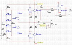
I had originally tried to build something similar to your idea : sense the voltage drop on the 0.22R (which is too low to be of any use) and then amplify it using a MC33072. I had referred the sense voltage to ground and the output was also referred to the ground, and had no idea what to do next.
The op-amp approach is better for a steeper protection scheme, ie a protection that will trigger suddenly , not gradually. Here is a half-finished schematic :
Attachments
I did not think the 0.22s would be a problem as they are less than 1/63 of the expected load of 13-14 Ohms.
The load is actual 13-14 ohms divided by the transformer ratio squared, so closer to .1 ohms. The load (15 ohms at 50v) draws 167 watts peak. So at 6 volts you need 27 amps peak! So the .22 ohm resistor will drop over 6 volts, or the full supply voltage. Try .03 ohms.
In reality it will be 2* 6V batteries.
Did I miss something? You want to drive a 160 watt amp with batteries?
Could you please explain to me what error condition the 82K resistor is meant to catch? With the current limiting in place there is no possible combination of Vce + Ic that will even go anywhere near the limits of the output transistors ?
Sorry for being slow
Well, the 82k feeds some current to the base of the protection transistor. Then there's the base current coming from the sense on the Re. If the sum of the currents is large enough, the protection triggers.
Now suppose Vout=0, and you short the output with signal. The protection will kick in when the voltage drop across Re, PLUS whatever comes from the 82k, opens up the protection transistor. So this has to be dimensioned for the output transistor max current at Vce=Vcc.
If you look at the Safe Operating Area of the transistor you will see that it can handle (much) more current with lower Vce; and (much) lower current when Vce is high.
So, imagine that Vout is (almost) up to +Vcc, then Vce is very small and the device can handle much more current. That is now automagically taken care off - the voltage across the 82k (= ~Vce) is small, the current through the 82k is smaller, and you can have more current through Re before the protection kicks in.
Opposite when Vout is almost down to -Vcc, then across the 82k is the full total supply, more current into the 82k and you only need a small current through Re to trigger the protection.
So this really is a VI limiter - reacting on both Ic and Vce.
jan
Last edited:
Did I miss something? You want to drive a 160 watt amp with batteries?
I must have misled you with a bad schematic - the expected load is 2000 Ohms at 50 V AC peak. The transformer will be 1:12 - so the load on the output stage will be in the range of 2000 / 144 = 14 Ohms. Sometimes for simulation purposes I remove the transformer and replace with a 15 Ohm resistor.
I did not think the 0.22s would be a problem as they are less than 1/63 of the expected load of 13-14 Ohms. The prototype is with 0.15R.
I am not sure if distortion will be an issue, but I have erred on the side of caution and have provided as much bias as necessary so that it looks good on the oscilloscope.
The previous stages use a split supply, and I just used that. In reality it will be 2* 6V batteries. Would a single supply make anything better ?
I had originally tried to build something similar to your idea : sense the voltage drop on the 0.22R (which is too low to be of any use) and then amplify it using a MC33072. I had referred the sense voltage to ground and the output was also referred to the ground, and had no idea what to do next.
The op-amp approach is better for a steeper protection scheme, ie a protection that will trigger suddenly , not gradually. Here is a half-finished schematic :
As cbdb mentioned, the load seen by the amp is that of the transformer under load. Try thinking in terms of power too. If the load is dissipating a given power then the amp must be supplying at least that plus losses.
A single supply is neither better nor worse, just another option maybe more suited to battery use. I take these are SLA type batteries. With a single supply the current limiting could go in either supply lead using a single low value sense resistor and opamp. Choice of opamp would be important as you would want it to work without auxilliary rails.
It's all quite a major design exercise really.
This is my first pass on this project. I had to make some arbitrary choices to start with.
I have just checked that a 12 V / 4Ah battery weighs as much as two 6V / 4Ah batteries, and the same again for 12V/1.2Ah or 12V/7Ah. There is not much to gain from choosing the one 12V over the two 6 V batteries.
I used the (V)I limiting mentioned above and it seems to work ok, I spent some time yesterday shorting the terminals just to make sure.
Battery choice will depend on current consumption and recharging time needed: currently 130mA on nominal load - but there is more circuitry coming.
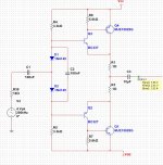
Hi again. I have modified the previous output stage with this one here, because this one approaches the rails better (produces greater voltage swing) even at very high loads - a typical load is 2R.
However now I am having trouble implementing a (V)I protection. The 0.1R are too small to produce a voltage that would open a current limit transistor. With 2R load the maximum voltage developed across the 0.1R is 200mV - way to low.
An option is to sense and amplify this voltage using an op-amp chip and then use another op-amp/comparator to compare it with a reference voltage and then trigger the current limit transistors. But this approach means two extra op-amp chip and 16 or more extra resistors.
Is there a clever way to do something similar to what we did in the previous page (with the VI limit) also here?
Attachments
Think about what a VI limiter is supposed to do.
One thing it is not supposed to do, is trigger when a valid audio signal is passing to a valid audio load.
200mV across 0r1 is only 2Apk output. Why would you want to limit @ ~2Apk into an 8r0 test load? Even more onerous is a short term transient into an 8ohm speaker. Allow upto 15Apk into a 8ohm speaker from a 100W amplifier (+-50Vdc supply rails).
Even more into a 4ohm speaker from it's 100W amplifier (+-40Vdc supply rails).
- Status
- This old topic is closed. If you want to reopen this topic, contact a moderator using the "Report Post" button.
- Home
- Amplifiers
- Solid State
- Load and device protection