Hi,
I have a Cyrus One issue 07 TOG. I checked the bias recently and I have a channel measuring 5/6 mV. The other channel is ok measuring 8mV.
I have the service manual, and so I read there that if the value is low you must put a 220ohm resistor across the R81/R82 (This resistor should be 130ohm if I remember right).
Well, the strange thing is that on my unit the R81/R82 are those kind of jumper/resistors...here is a pix...
http://img857.imageshack.us/img857/5513/img0563vf.jpg
...if I check these resistors with my DVM i read 0....
If I put the resistor across the pins...nothing happens to the bias...
Anybody has the same issue as me?
Referring to the schematic on Geoff Moss's site below, you have R81 replaced with that link so you cant read across the test point anyway. Is this mod. the same in both channels? (R82) If so, someone has tried to change the bias before you and been unsuccessful.
The schematic suggests you replace the link resistor, not just parallel a short circuit. It could be worthwhile returning the values to orignal, unless the parts seem original manufacturers modifications.
http://www.tcaas.btinternet.co.uk/cyrus1pwr.gif
The schematic suggests you replace the link resistor, not just parallel a short circuit. It could be worthwhile returning the values to orignal, unless the parts seem original manufacturers modifications.
http://www.tcaas.btinternet.co.uk/cyrus1pwr.gif
hi Ian,
I bought this amp new in 1996, and I am the only owner. I think that this is 100% original. This is the schematic for my version
http://img688.imageshack.us/img688/6865/hfecyrusoneservice2flat.jpg
Here is an overview of my amp:
http://img84.imageshack.us/img84/8545/img7505b.jpg
...as you can see the R81 and R82 are the same type of the X21/X22, etc.....
I was thinking about changing the link with a 130ohm resistor...but I'm afraid to blow everything up!
Referring to the schematic on Geoff Moss's site below, you have R81 replaced with that link so you cant read across the test point anyway. Is this mod. the same in both channels? (R82) If so, someone has tried to change the bias before you and been unsuccessful.
The schematic suggests you replace the link resistor, not just parallel a short circuit. It could be worthwhile returning the values to orignal, unless the parts seem original manufacturers modifications.
http://www.tcaas.btinternet.co.uk/cyrus1pwr.gif
Looking at the picture and comparing them to the schematic reveals that your amp has different resistors.
R81/R82 carry only a black ring as far as I can see in the picture. This means they're 0R resistors. That would explain why parallelling another resistor to them with has no effect on the bias current, you cannot lower 0R any further
R83/R84 seem to carry white-red-black-black, or 920R, not 680R as per the schematic.
R85/R86 seem to carry red-blue-black-brown, or 2k6, not the 3k6 from the schematic.
Since you're the first owner, I expect it left the factory that way.
If the amp sounds OK, I wouldn't touch it. Since this amp hasn't got potmeters here, the slighly lower bias current in one channel might have been like that from new.
"If it ain't broke, don't fix it."
Last edited:
Hi jitter,
actually, I recapped the ampli...the pix I posted is my unit before the recapping. Actually the ampli works fine, with a nice and warm sound. I was just curious how I could adjust the bias on this unit...from what you wrote, it looks like this ampli has fixed bias...am I right?
QUOTE=jitter;3002197]Looking at the picture and comparing them to the schematic reveals that your amp has different resistors.
R81/R82 carry only a black ring as far as I can see in the picture. This means they're 0R resistors. That would explain why parallelling another resistor to them with has no effect on the bias current, you cannot lower 0R any further
R83/R84 seem to carry white-red-black-black, or 920R, not 680R as per the schematic.
R85/R86 seem to carry red-blue-black-brown, or 2k6, not the 3k6 from the schematic.
Since you're the first owner, I expect it left the factory that way.
If the amp sounds OK, I wouldn't touch it. Since this amp hasn't got potmeters here, the slighly lower bias current in one channel might have been like that from new.
"If it ain't broke, don't fix it."[/QUOTE]
Hi,
I think R81/82 have been replaced by "mystery" components that are in
fact dead shorts, and allow a component stuffing machine to insert PCB
links in the same way as real resistors.
To compare real bias voltages between channels measure the DC voltage
across C51 and /or the voltage across the 0.22R output resisistors.
FWIW replacing a short with 130R in the "Vbe muptiplier" will reduce bias.
rgds, sreten.
Hi,
I think R81/82 have been replaced by "mystery" components that are in
fact dead shorts, and allow a component stuffing machine to insert PCB
links in the same way as real resistors.
I doubt such a machine would have been used on low volume production.
But who knows, all links seem to be named X.. and close by is another 0R resistor in the position named X30/X31.
To compare real bias voltages between channels measure the DC voltage
across C51 and /or the voltage across the 0.22R output resisistors.
FWIW replacing a short with 130R in the "Vbe muptiplier" will reduce bias.
Why would Cyrus have chosen to deviate from the schematics? Or is it that the schematics from the One issue 7 from Geoff Moss aren't actually from an issue 7?
Last edited:
I posted an Issue 07 and TOG schematics (same as amp)...not Issue 1....
ah...ok...sorry, you edited your post....
The question why cyrus deviate from the schematics is the key question...what I could add is that my unit actually was assembled in Taiwan...so maybe they messed up the things...but why?
ah...ok...sorry, you edited your post....
The question why cyrus deviate from the schematics is the key question...what I could add is that my unit actually was assembled in Taiwan...so maybe they messed up the things...but why?
The schematics posted by pampalini are from an issue 1 (wouldn't we nowadays call that "revision"?).
Last edited:
Hi jitter,
actually, I recapped the ampli...the pix I posted is my unit before the recapping. Actually the ampli works fine, with a nice and warm sound. I was just curious how I could adjust the bias on this unit...from what you wrote, it looks like this ampli has fixed bias...am I right?
Well, the amps I've owned all had potmeters for setting the quiescent current. But the service manuals always give one particular value, so effectively it's fixed too.
Yes, I edited my post. I saw "issue 1" vertical far left in your schematic, but realized this issue is of the service manual itself, not the amp.
The question why cyrus deviate from the schematics is the key question...
Perhaps with the resitors in the schematic the right quiescent current couldn't be achieved with the used transistors. Variation between transistors is why there usually is a potmeter for the qc-setting. After replacing the output transistors with new ones, the qc usually needs to be corrected.
what I could add is that my unit actually was assembled in Taiwan...so maybe they messed up the things...but why?
So the proud "Made in Scotland" sticker only applies to the toroid it's stuck on...
In days when Mission owned Cyrus, they had some difficult changes to make. Now it is an independent business, promoting models from Cyrus 5 on,IIRC as high-end, expensive class equipment.
I agree - leaving bias fixed as it is should be fine unless the semis need replacement.
There are 3 good reasons not to use pots for adjusting bias.
*Owners and amateur techs make unwise adjustments causing damage.
*Quality of cheap pots is poor so values drift or they fail mechanically.
*They cost more than fixed resistors.
Last edited:
Yes, i know. But I have only replaced the caps, not the final transistors....and they are the PT7, a custom made transistor that ST did for cyrus, based, i think, on the BUV28 transistor....
I guess I should check the resistor's value in my unit to see if there are differences from the service manual part list, as suggested in another post...It really get me nervous that I cannot adjust the bias!
I guess I should check the resistor's value in my unit to see if there are differences from the service manual part list, as suggested in another post...It really get me nervous that I cannot adjust the bias!
Perhaps with the resitors in the schematic the right quiescent current couldn't be achieved with the used transistors. Variation between transistors is why there usually is a potmeter for the qc-setting. After replacing the output transistors with new ones, the qc usually needs to be corrected.
So the proud "Made in Scotland" sticker only applies to the toroid it's stuck on...
Hi pampalini
Do you believe the value has changed from 8 to 5-6 mV Vre because of changing caps?
It seems to have been that way or close since manufacture. After all, with fixed resistors already in the board as you have, there is no way they could have been trimmed except by selection of semis. That selection could well be just a tightened range of Vbe to limit the inevitable bias variation.
Perhaps you are expecting a precision that is not possible or necessary in this Quasi EF triple. Quasi-complementary stages have different parameters because one bias current level cannot match both upper and lower half which have different switching characteristics. These require different bias levels for optimum low distortion. Few DIY guys seem to want that quality anyway but whatever you believe is optimum for an EF or CFP design cannot be done here.
If random parts variation is not the problem and you did measure 8 mV in both channels before, then the change will be in the thermal compensation but not in fixed links or resistors. Perhaps replacing the cover for full warm-up gives different bias levels. Check drift over the full warm-up cycle for interest and measure quickly after removing case etc.
If you just want to feel everything measures identical, then adjust the potentiometer formed by R83, R85 to increase bias. Try briefly paralelling R83 with 10-20 X 680R while the meter monitors Vre. I suggest reading across both R107A&B and double the voltage expected to improve your reading accuracy. This should be a small adjustment to see what is required. Obviously this will be awkward, so IC clips are best but take care.
Yes, i know. But I have only replaced the caps, not the final transistors....and they are the PT7, a custom made transistor that ST did for cyrus, based, i think, on the BUV28 transistor....
I guess I should check the resistor's value in my unit to see if there are differences from the service manual part list, as suggested in another post...It really get me nervous that I cannot adjust the bias!
Why would that make you nervous? Was this the first time you measured the bias current or did you measure it before? If so, was there the same discrepancy between the L and R channels?
More issues
A small piece of history here: (#30) http://www.diyaudio.com/forums/solid-state/89636-cyrus-1-amp-later-version-3.html
Can you tell us exactly where Q39,40 are located? These are the bias regulator transistors and in many amps they are
fixed to the output stage transistors (EF) or the drivers (CFP) when you expect any precision from bias control.
Otherwise, as in many quasi-complementary stages, bias can drift depending on the heat inside the case, and air flow.
Anything can disturb bias unless there is reliable thermal signal from the output stage either in steady air flow or radiant
heat transfer that results in the correct coefficient in (-) mV/degree C to reduce bias automatically as the output stage
temperature rises. The transistors will be in different locations, hence will drift differently.
If you remove the case, the air temperature drops and allowance must be made with adjustment, so service procedure
may be critical for setting. If there are no particular precautions with time or case temperature needed, you know the
setting cannot be critical when Q39/40 are not in physical contact with the output stage.
Last edited:
A small piece of history here: (#30) http://www.diyaudio.com/forums/solid-state/89636-cyrus-1-amp-later-version-3.html
Can you tell us exactly where Q39,40 are located? These are the bias regulator transistors and in many amps they are
fixed to the output stage transistors (EF) or the drivers (CFP) when you expect any precision from bias control.
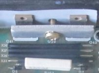
Look just under the screw head, the silkscreen shows Q39. I guess Q39 is mounted to the heatsink in between the power transistors Q41 and Q43.
Otherwise, as in many quasi-complementary stages, bias can drift depending on the heat inside the case, and air flow.
Anything can disturb bias unless there is reliable thermal signal from the output stage either in steady air flow or radiant
heat transfer that results in the correct coefficient in (-) mV/degree C to reduce bias automatically as the output stage
temperature rises. The transistors will be in different locations, hence will drift differently.
Agreed.
If you remove the case, the air temperature drops and allowance must be made with adjustment, so service procedure
may be critical for setting. If there are no particular precautions with time or case temperature needed, you know the
setting cannot be critical when Q39/40 are not in physical contact with the output stage.
In the service manual of (e.g.) the Marantz PM40(SE) there's a table listing what the reading of the bias current (called idling current in that manual) should be at certain time intervals after power up. It should stabilize after 4 mins.
Q39 and Q40 appear to be mounted to the heatsink, so measure the bias current with the case installed and allow temp to stabilize before taking measurements.
Attachments
Hi, Sorry, but I am out of town for the week end, and I do not the have the amp with me ")
Unfortunately I never measured the bias before, so I cannot compare the before/after values.
...and of course when I measured the bias I waited at least 20 min. to let the current stabilize....
I read the thread suggested by Ian, and the R85 resistor could be the solution...
As soon I will be back home I will take some measurement...thanks a lot for the help
Thanks Jitter, that's excellent help. IME, Quasi stages don't use direct fixing to the heatsink - so I've tried to describe the difference to standard EF & CFP types, You can't do the CFP like that without a disaster and Quasi is half CFP, half EF. So what happens? The manufacturer does a "fudge" and places the sense transistor a little distance from the sink, so the thermal transfer coefficient is reduced or has a different characteristic. This Cyrus is interesting as it is a triple which is mostly EF so I will guess the transistors are just sitting close, not fixed. If I'm wrong, I owe you a beer,Look just under the screw head, the silkscreen shows Q39. I guess Q39 is mounted to the heatsink in between the power transistors Q41 and Q43........In the service manual of (e.g.) the Marantz PM40(SE) there's a table listing what the reading of the bias current (called idling current in that manual) should be at certain time intervals after power up. It should stabilize after 4 mins.......Q39 and Q40 appear to be mounted to the heatsink, so measure the bias current with the case installed and allow temp to stabilize before taking measurements.

The PM40 I haven't worked on but I have a brand new K1-Pearl Lite to listen to for a week or so but no schematic. It does sense the heatsink as far as I can see without voiding warranty. PM7001 is definitely EF as the schematic is everywhere. (Nice sounding amplifiers those Japanese Kenwood Marantz builds.) EF must have sensors clamped to the heatsink or better, right on a power transistor. It's the most common linear amplifier type by a huge margin.
@ pampalini, thanks for checking in, you must have sensed we were talking about you. Check that was R83, but I guess you could increase R85 to some effect.
Thanks Jitter, that's excellent help. IME, Quasi stages don't use direct fixing to the heatsink - so I've tried to describe the difference to standard EF & CFP types, You can't do the CFP like that without a disaster and Quasi is half CFP, half EF. So what happens? The manufacturer does a "fudge" and places the sense transistor a little distance from the sink, so the thermal transfer coefficient is reduced or has a different characteristic. This Cyrus is interesting as it is a triple which is mostly EF so I will guess the transistors are just sitting close, not fixed. If I'm wrong, I owe you a beer,
To be honest I'm not that at home in amplifier design so skimmed through Douglas Self's amp handbook first.
I agree that the transistor might not have been attached to the heatsink, I expect to have seen it sitting in plain view had it been attached. Pampalini, if you're back, could you take a better pic of the heatsink area, preferably also from the bottom side?
Edit: according to Geoff Moss's schematic, Q39 is a 2SC1775 which has a TO-92 case. With that in mind, I think it's most likely that it's close to the heatsink, but not clamped to it.
The PM40 I haven't worked on but I have a brand new K1-Pearl Lite to listen to for a week or so but no schematic. It does sense the heatsink as far as I can see without voiding warranty. PM7001 is definitely EF as the schematic is everywhere. (Nice sounding amplifiers those Japanese Kenwood Marantz builds.)
PM40(SE) is an emitter follower too, as is the PM80(SE)... I think most Marantz amps are.
Yes, Marantz amps sound nice, I always end up with one.
@ pampalini, thanks for checking in, you must have sensed we were talking about you. Check that was R83, but I guess you could increase R85 to some effect.
Personally, I would change the resistors that are in now for the values that are in the schematics and see what that does to the bias current. Then I'd try to adjust the bias current by parallelling R81/R82 with the value suggested in the service manual and see what happens. If it doesn't work as intended, it might explain why Cyrus didn't use the resistors as per the schematics.
Last edited:
This is what sreten pointed out; R81,82 has been removed completely and still the bias is too low, so replacing it as I first thought,..... change the resistors that are in now for the values that are in the schematics and see what that does to the bias current. Then I'd try to adjust the bias current by parallelling R81/R82 with the value suggested in the service manual and see what happens. If it doesn't work as intended, it might explain why Cyrus didn't use the resistors as per the schematics.
like you, won't work. You only have R83,84 to reduce or R85,86 to increase. It's a voltage divider in a sense.
The trim resistor R81,82 has been removed in manufacture so the service manual is simply wrong for this board. The bias sub-circuit
increases current in the bias transistor to reduce bias voltage across bases Q27,29 and Q28,30. That's the negative coefficient part.
Finally, this reduces bias current in the output transistors which is what we need when bias and the output transistor conductance
has been increased by heating.
I think pampalini will get a grip on that and make suitable substitutions but personally, I think it is not critical to sound or operation
and is within the manufacturer's spec. If you don't like the manufacturer's spec, you don't like his amp. either. This is not a design
that can use bias precision - look at the Naim sites on the web and see how nobody agrees except those who know that factory
setting is safe and guys who play don't understand control circuit limitations in real amplifiers.
- Home
- Amplifiers
- Solid State
- Cyrus One Bias Issue