hey there, i have a problem with my amp (integrated KT88PP, with 5814A as input and drivers).
i changed the circuit with diffent valves, added ccs to the input stage and reduced the resistors R7 & R8 in the powersupply to maintain the designed voltages.
If i start testing with signals <40Hz it starts oscillating at about1 Hz. (visible on the bias balance leds) and there is some "squeeging" at f>2kHz.
it must be connected to the smaller resistance in the supply (R7 is reduced from 1k8 t0 560r, R8 is reduced from 6k8 to 3k9).
My question now is, can i improve the supply by changing to a regulator design?
i think the 21st Century Maida Regulator thread on DIY Audio.
looks promising, or do you know better or simpler designs
or maybe use 2 of these regs to supply the driver and input tubes on each channel seperately. i would need about 144mA each side for bias.
possibly its enough to reduce the voltage on input B+ from 320 to 280V, since that would be enough for the ccs to operate? any help is appreciated")
Thanks
i changed the circuit with diffent valves, added ccs to the input stage and reduced the resistors R7 & R8 in the powersupply to maintain the designed voltages.
If i start testing with signals <40Hz it starts oscillating at about1 Hz. (visible on the bias balance leds) and there is some "squeeging" at f>2kHz.
it must be connected to the smaller resistance in the supply (R7 is reduced from 1k8 t0 560r, R8 is reduced from 6k8 to 3k9).
My question now is, can i improve the supply by changing to a regulator design?
i think the 21st Century Maida Regulator thread on DIY Audio.
looks promising, or do you know better or simpler designs
or maybe use 2 of these regs to supply the driver and input tubes on each channel seperately. i would need about 144mA each side for bias.
possibly its enough to reduce the voltage on input B+ from 320 to 280V, since that would be enough for the ccs to operate? any help is appreciated
Thanks
Attachments
Last edited:
Here are the circuits, the reason for me thinking its the suppy is that i noticed oscillations after i changed the resistors..
The amp is not really "finished" i built it and i have to adjust gain shelving and nfb.
(and its oscillating with and without nfb at described frequencies, no matter what values i use for the shelf.)
The amp is not really "finished" i built it and i have to adjust gain shelving and nfb.
(and its oscillating with and without nfb at described frequencies, no matter what values i use for the shelf.)
Attachments
make better CCS - made of two BJT's
I'm lazy for remembering , but maybe proper name is Widlar or something
it seems pictured here : Google Image Result for http://upload.wikimedia.org/wikipedia/commons/thumb/8/84/Widlar_Patent.PNG/350px-Widlar_Patent.PNG
in that case make R31 group of two series resistors (say 100K+120K) and put filtering cap from their junction to pos rail
Last edited:
Another possibility is that the subsonics are another artifact, in addition to the squeeging, of the parasitic oscillation. It's common for grid coupling time constants to charge up with grid forward conductance and then discharge at about that rate. A relaxation oscillator of sorts.
I'd be tempted to fix the parasitics first, then see if the subsonics are automagically cured too.
All good fortune,
Chris
I'd be tempted to fix the parasitics first, then see if the subsonics are automagically cured too.
All good fortune,
Chris
If i start testing with signals <40Hz it starts oscillating at about1 Hz. (visible on the bias balance leds) and there is some "squeeging" at f>2kHz.
Have you changed the loop gain of the circuit? Which valves were replaced, which valves were used originally and what were they replaced with?
My question now is, can i improve the supply by changing to a regulator design?
i think the 21st Century Maida Regulator thread on DIY Audio.
looks promising, or do you know better or simpler designs
A zener stack with an emitter follower output is the simplest I can think of. It's not the best performer, but it's the simplest. I actually went through quite a few regulator designs before designing the 21st Century Maida. It's a rock solid regulator.
However, before changing to a regulator, let's fix your amp. As Jan points out, the motor boating and squeeging are caused by instability in the circuit.
i would need about 144mA each side for bias.
possibly its enough to reduce the voltage on input B+ from 320 to 280V
Yeah, the 21st Century Maida Reg can do that just fine. No issues there.
Maybe post the amp circuit instead. Motortboating comes from a feedback (positive) at those frequencies. probably better to verify that first, getting to the root cause.
Couldn't have said it better.
make better CCS - made of two BJT's
I'm lazy for remembering , but maybe proper name is Widlar or something
The CCS'es could be improved, but I don't think that's the source of the problems. Especially, if they provide a reasonably constant current they way they're currently configured. This can be confirmed by measuring the voltages across the emitter resistors.
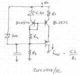
However, if the CCS'es are causing trouble, I suggest replacing them with attached. It's a CCS that I've been playing with lately. It provides a nice, temperature compensated current source. It's fairly low gain compared to the one Zen Mod is referring to (I believe that one what Morgan Jones calls the "Ring of Two"). This is completely intentional. I've had issues with the Ring of Two oscillating on transients. The Ring of Two is also not temperature compensated (as the transistors heat up, the bias current will vary significantly).
If you choose to use my CCS, set up the current in R2, R3 around a few hundred uA (limit the dissipation in R3). Calculate R2 such that you get roughly 10 V across it. Also, keep the two PNP's close together - preferably thermally connected to each other. The output impedance of this current source is extremely high - exactly what you want for a CCS - due to the cascode (the PMOS). You can turn the circuit upside down and use NPN/NMOS devices for a current sink if you like.
But to get back to your amp. Are you able to run it with the global negative feedback disconnected? If that's possible, then you definitely have stability issues.
~Tom
Attachments
Last edited:
Thanks for the replies,
I’ve been away for work this week, but back on track now..
@jannemann : no difference with R1 shorted.
@ Chris Hornbeck : „I'd be tempted to fix the parasitics first, then see if the subsonics are automatically cured too.”
I was hoping it works the other way around too, since I am limited with my test gear (pete millets soundcard interface on my pc, and a digital oscilloscope with less than average bandwidth…)
@tomchr : I replaced V1,V2,V3,V4, all were originally 6CG7 (see original circuit attached) and I wanted to use the 5814A I have.
If I calculated the gain right, it was about 6.2 for V1 in the original circuit, with 5814 paralled @5mA each half I get gain=13.6 , so maybe that’s already causing my problem.
without feedback it gets worse....
Morgan jones writes that interstage decoupling caps can cause motor boating on Williamsons, so I detached C25 for testing with 5kHz and 20Hz,and it changed :
the sqeeging gets worse, the motorboat gets smaller( valves start drawing grid current at about 5V Vo instead of 2,8V).
I have not changed the value of C23 yet. I should have some time this weekend.
greetings from a finally sunny germany
I’ve been away for work this week, but back on track now..
@jannemann : no difference with R1 shorted.
@ Chris Hornbeck : „I'd be tempted to fix the parasitics first, then see if the subsonics are automatically cured too.”
I was hoping it works the other way around too
, since I am limited with my test gear (pete millets soundcard interface on my pc, and a digital oscilloscope with less than average bandwidth…)@tomchr : I replaced V1,V2,V3,V4, all were originally 6CG7 (see original circuit attached) and I wanted to use the 5814A I have.
If I calculated the gain right, it was about 6.2 for V1 in the original circuit, with 5814 paralled @5mA each half I get gain=13.6 , so maybe that’s already causing my problem.
without feedback it gets worse....
Morgan jones writes that interstage decoupling caps can cause motor boating on Williamsons, so I detached C25 for testing with 5kHz and 20Hz,and it changed :
the sqeeging gets worse, the motorboat gets smaller( valves start drawing grid current at about 5V Vo instead of 2,8V).
I have not changed the value of C23 yet. I should have some time this weekend.
greetings from a finally sunny germany
Attachments
In your first schematic there is mentioned that the global NFB should be 14 dB.
Now you have changed tubes and added CCS. It is obvious that the amount of negative feedback is not 14 dB anymore.
Measure the gain difference when R10 is short circuited and normal.
What is the result ?
If you short circuit R10, is there still mororboating ?
Now you have changed tubes and added CCS. It is obvious that the amount of negative feedback is not 14 dB anymore.
Measure the gain difference when R10 is short circuited and normal.
What is the result ?
If you short circuit R10, is there still mororboating ?
Hi,
I did the math and went through the gain of the stages, everything seems fine.
My Output stage is biased at -60V, 120Vpp , or 41.66Vrms is the maximum I need from the driver stage. I measure a gain of 11.2x on the driver stage, so max needed Vi on the drivers is 3.72Vrms. V1 and V2 are set to a gain of about 14(open loop) .
Vin of V2 = 0.266V max, and I need Vo of V1 to be 1.62V to power the Vol pot.
Vin of V1 = 0.118V and that gives me the desired 0.2V rms (by the original design) at the Input terminals.
I increased R8 in the Powersupply and changed the Resistors in the CCS to match. i now have 285V B+ (Input Stage) .
That didnt solve anything though.
Hello,
@Chris
there is LF Oscillation and the squeeging with the feedback loop open,
there is LF Oscillation as soon as i feed a signal <40Hz from the pc to the amp. it's visible at the bias balance leds.
the squeeging becomes audible when i feed f>2khz from the pc, and is caused by the right channel output tube. (it get more quiet when i touch the envelope of the tube with the fingernail.)
the oscillations get less when nfb is conected.
if i disconnnect c26 all oscillation stops at the output. if i measure @c26, i can still see the oscilloscope flickering at LF, so i think the oscillations are caused.in v1/v2.
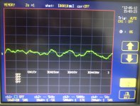
the B+ doesn't look great on the oscilloscope, there is ac, maybe 5mVpp,and sometimes there are peaks of 15-20mvpp. its not a clean trace either, maybe 10000Hz on top
@df96: increasing the value of the cap to 3.5uF doest change anything
@Chris
there is LF Oscillation and the squeeging with the feedback loop open,
there is LF Oscillation as soon as i feed a signal <40Hz from the pc to the amp. it's visible at the bias balance leds.
the squeeging becomes audible when i feed f>2khz from the pc, and is caused by the right channel output tube. (it get more quiet when i touch the envelope of the tube with the fingernail.)
the oscillations get less when nfb is conected.
if i disconnnect c26 all oscillation stops at the output. if i measure @c26, i can still see the oscilloscope flickering at LF, so i think the oscillations are caused.in v1/v2.
the B+ doesn't look great on the oscilloscope, there is ac, maybe 5mVpp,and sometimes there are peaks of 15-20mvpp. its not a clean trace either, maybe 10000Hz on top
@df96: increasing the value of the cap to 3.5uF doest change anything
Attachments
Too small a change; it might change the oscillation frequency a bit but not stop it. Try 22uF or 47uF so that the LF pole introduced by the CCS is moved well away from its current frequency. Do the change to one CCS, then both. You might find that you need significantly different values in the two CCS, to separate the poles.yurgs said:@df96: increasing the value of the cap to 3.5uF doest change anything
I note that C27 has 1M across it. This suggests that the designer knows that LF stability may be a problem, although this relates to the amp as a whole.
there is LF Oscillation and the squeeging with the feedback loop open,
if i disconnnect c26 all oscillation stops at the output. if i measure @c26, i can still see the oscilloscope flickering at LF, so i think the oscillations are caused.in v1/v2.
Excellent; you've ruled out all the difficult stuff. The first two stages share two unintended circuit paths; both B+ and "ground" are undecoupled. Without the complication of the current sources, the B+ path is short and difficult to cause anything but negative feedback. The "ground" path is unknown, and common impedance can cause a positive feedback. It appears as a magically perfect zero impedance in schematics; the real implementation is unknown to all but the builder. Might be worth exploring if the CCS changes don't do the trick.
Also, what's the value, and purpose, of R13? Seems to degrade supply impedance.
All good fortune,
Chris
Yes, R13 (value?) seems to increase the impedance of the 320V supply at subsonic frequencies - exactly not what is wanted. The CCS then pass this through with some phase shift and we then have an LF oscillator. You could try reducing the value of C22 down to around 0.22uF; alternatively increase it to 10uF. The aim in either case is to move its pole away from the CCS poles. This circuit as is seems to have lots of CR networks with rolloffs around 2-3Hz - asking for trouble as the phase shifts all add up!
ok, the first step would be to take the negative feedback out of the circiut for troubleshooting.
never "fix" a motor boating problem by using negative feedback
now on your power supply schematic, Remove R18 and place a jumper wire.
take a .1 250V ploypropolene cap and apply it from point E of the heater transformer ( heater 0V ) to chassis ground.
on the mains input open the connection from FG to chassis, insert a .01 uf @ 1KV from FG of IEC connector (E) to ground.
now turn on the unit, the motor boating should be gone. now re attach the negative feedback if you need to lower the gain.
- Status
- This old topic is closed. If you want to reopen this topic, contact a moderator using the "Report Post" button.
- Home
- Amplifiers
- Tubes / Valves
- My amp is motorboating, improve it with b+ regulator ?