As title says I did buy this eBay DAC board and associated enclosure from along1986090. Used my transformers.
CS4398 with CS8416+CM102s, provides coaxial SPDIF and USB inputs.
First impressions:
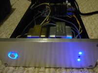
Enclosure definitelly well done, with (almost) all necessary hardware, holes in exact locations to match the board. Kind of long (10", plus 1/4" front aluminium plate), I guess it can be used to add a dedicated headphones amp.
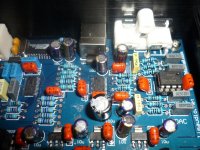
I did buy the pre-solderd board. Inspected with the magnifier glass showed an OK grade of soldering. PCB is in filled ground technique and parts are like shown in the picture.
Initial tests had a sligtly distorted signal and analized with my E-MU1820m showed a really bad signal. I did replace the 5532 that was on board with LM4562 that I hade around and everything started to look better. I suspect that the 5532 was either a fake or a damaged exemplar. There is no capacitor or resitors on OpAmp outputs, so it is easy to be damaged.
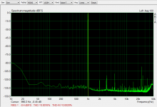
At -2dB looks decent. The output stage overloads my ADC input at higher than -2dB (all the other DAC's that I tested didn't manage to do that).
The output stage is not done per recomended schematics in the datasheet.
USB input:
CM102 locks only onto 16bit/48kHz signals. 16bit/44.1kHz is not supported in Windows7 mixer (WASAPI).
If looses the connection with the PC, static noise is outputted till the next power off/on cycle. The automatic switching could be done better I guess...
Altough in Win 7 there is no need for drivers, here is a package that provides a little more that basic USB. This driver looks like it does the resampling to 48kHz automatically.
Coax SPDIF:
Locks on 44.1-96kHz, 16 or 24 bit. I don't have a SPDIF source capable of 192kHz to fully test the CS8416.
Using Foobar with resampling to 48kHz would allow USB connection to work at any rate, but I do prefer the coax.
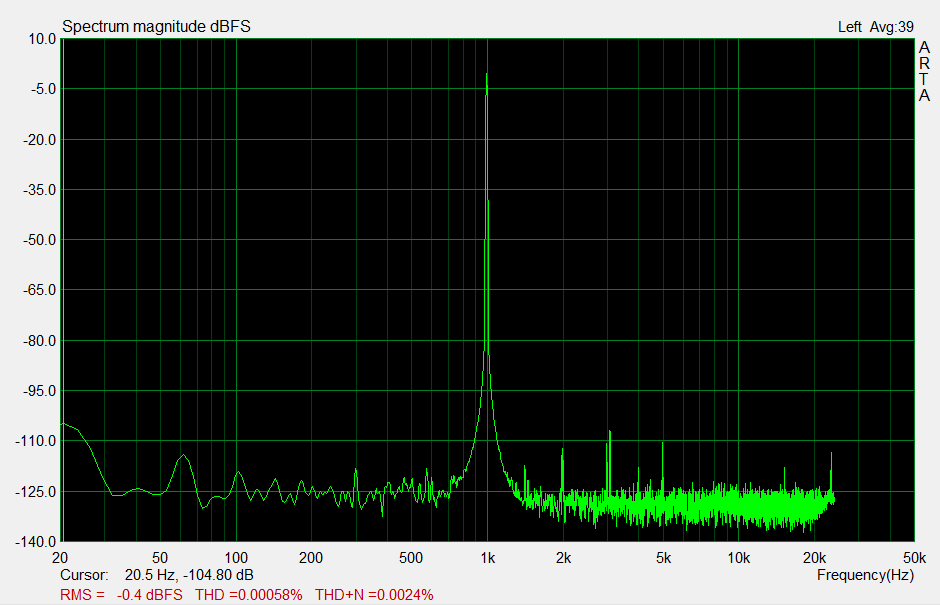
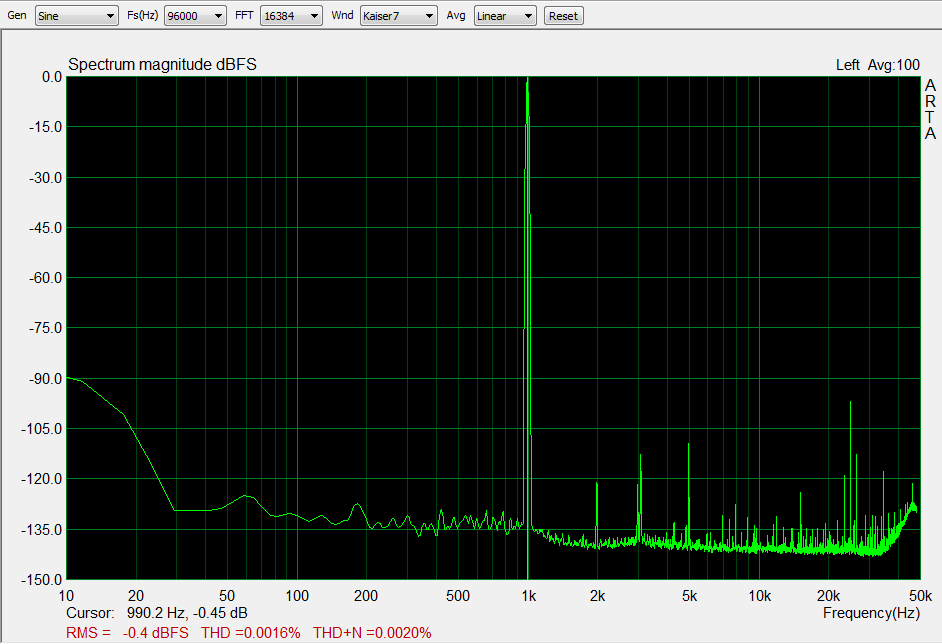
All in all, sounds decent, especially for the price. THD+N with LM4562 is at -94dB. OpAmp upgrade is strongly recomended and looks like some of the AC grid noise could be reduced by better filtering.
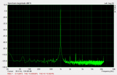
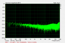
Direct coupling of the outputs leaves some higher levels of 10Hz noise creep into the output chain as seen in the coax graph (at USB I forgot to extend the range below 20Hz).
The seller give the schematics (at my request).
CS4398 with CS8416+CM102s, provides coaxial SPDIF and USB inputs.
First impressions:
Enclosure definitelly well done, with (almost) all necessary hardware, holes in exact locations to match the board. Kind of long (10", plus 1/4" front aluminium plate), I guess it can be used to add a dedicated headphones amp.
I did buy the pre-solderd board. Inspected with the magnifier glass showed an OK grade of soldering. PCB is in filled ground technique and parts are like shown in the picture.
Initial tests had a sligtly distorted signal and analized with my E-MU1820m showed a really bad signal. I did replace the 5532 that was on board with LM4562 that I hade around and everything started to look better. I suspect that the 5532 was either a fake or a damaged exemplar. There is no capacitor or resitors on OpAmp outputs, so it is easy to be damaged.
At -2dB looks decent. The output stage overloads my ADC input at higher than -2dB (all the other DAC's that I tested didn't manage to do that).
The output stage is not done per recomended schematics in the datasheet.
USB input:
CM102 locks only onto 16bit/48kHz signals. 16bit/44.1kHz is not supported in Windows7 mixer (WASAPI).
If looses the connection with the PC, static noise is outputted till the next power off/on cycle. The automatic switching could be done better I guess...
Altough in Win 7 there is no need for drivers, here is a package that provides a little more that basic USB. This driver looks like it does the resampling to 48kHz automatically.
Coax SPDIF:
Locks on 44.1-96kHz, 16 or 24 bit. I don't have a SPDIF source capable of 192kHz to fully test the CS8416.
Using Foobar with resampling to 48kHz would allow USB connection to work at any rate, but I do prefer the coax.
All in all, sounds decent, especially for the price. THD+N with LM4562 is at -94dB. OpAmp upgrade is strongly recomended and looks like some of the AC grid noise could be reduced by better filtering.
Direct coupling of the outputs leaves some higher levels of 10Hz noise creep into the output chain as seen in the coax graph (at USB I forgot to extend the range below 20Hz).
The seller give the schematics (at my request).
Attachments
Last edited:
I don't have measurements saved, but it was OK with the LM4562. For some reason, the original 5532 sucked bad. I still have it in a bin ") I will do some measurements latter.
I will do some measurements latter.
I don't know why, CS8416 in my board (in hardware mode) doesn't go over 96kHz. Maybe is the same as for the WM8804 receiver.
I will do some measurements latter.I don't know why, CS8416 in my board (in hardware mode) doesn't go over 96kHz. Maybe is the same as for the WM8804 receiver.
Last edited:
Your graph is weird, looks like noise... I will try again, with another source.
Be carefull, if you use a player that uses DirectSound to send the audio data, DS will resample the datarate to match what your device "reports" that is capable of or what is set in Windows mixer. I am using Foobar because I can choose exactly what path to use for data.
Be carefull, if you use a player that uses DirectSound to send the audio data, DS will resample the datarate to match what your device "reports" that is capable of or what is set in Windows mixer. I am using Foobar because I can choose exactly what path to use for data.
Last edited:
Interesting.
I have one of these due any day now (reached NY yesterday).
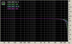
One thing that stood out to me was the original graphs shown by the seller had the frequency response going past 40KHz at -3dB with the sample rates at 44.1KHz and 48KHz.
I thought that was not possible according to Niquest-Shannon sampling theorem.
Certainly the LP filter could allow it and the plots for 96Khz and 192KHz would be accurate in that region.
But would the 44.1 and 48KHz plots?
I bought just the assembled DAC board.
I have one of these due any day now (reached NY yesterday).
One thing that stood out to me was the original graphs shown by the seller had the frequency response going past 40KHz at -3dB with the sample rates at 44.1KHz and 48KHz.
I thought that was not possible according to Niquest-Shannon sampling theorem.
Certainly the LP filter could allow it and the plots for 96Khz and 192KHz would be accurate in that region.
But would the 44.1 and 48KHz plots?
I bought just the assembled DAC board.
Attachments
Near 100 years of sampling theorem says it is impossible.
You have to sample twice the highest frequency of interest to reconstruct it without massive distortion.
At 44.1KHz, the highest frequency that can be passed undistorted is 22.05KHz (minimal distortion actually because one can not guarantee synchronization between the frequency of interest and the sample clock). In reality 22.05KHz will be distorted as well so normal procedure is to filter below this.
There is a good explanation here:
Nyquist?Shannon sampling theorem - Wikipedia, the free encyclopedia
Great - finally a separate thread for this DAC
And for my contribution;
High-res photos of the board:
FRONT
BACK
Those come in handy for the modifications...
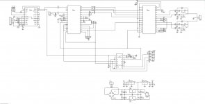
And the SCHEMATIC which is a little old and it's missing D+3,3 PSU section, but the rest is ok...
Concerning higher sample rate playback (above 96kHz);
On the board above CS8416 pin 20 (TX) is set high, this enables faster Phase Detector Update Rate - you get less jitter, but it will play only up to 96kHz (108kHz according to Cirrus)...
More on the matter in the official "papers"; http://www.cirrus.com/en/pubs/appNote/AN339REV1.pdf
Some say it works with higher sample rate - possibly a different revision of the board?
All in all - a great little DAC for a few pennies
And for my contribution;
High-res photos of the board:
FRONT
BACK
Those come in handy for the modifications...
And the SCHEMATIC which is a little old and it's missing D+3,3 PSU section, but the rest is ok...
Concerning higher sample rate playback (above 96kHz);
On the board above CS8416 pin 20 (TX) is set high, this enables faster Phase Detector Update Rate - you get less jitter, but it will play only up to 96kHz (108kHz according to Cirrus)...
More on the matter in the official "papers"; http://www.cirrus.com/en/pubs/appNote/AN339REV1.pdf
Some say it works with higher sample rate - possibly a different revision of the board?
All in all - a great little DAC for a few pennies
Schematic w/ 3.3V supply
Since there is no copyright on the schematic I'll upload it.
Oops, schematic too big. I'll downsize it and upload it.
My board has been hung up in USPS for the last four days. I was hoping to get it today but no joy.
Also in the event that someone finds this thread later on, there is another thread that has a lot of good points that should apply to this board as well ..
http://www.diyaudio.com/forums/digital-source/186245-dac-2496-ak4393-dac-kit-cs8416-ak4393-5532-a.html
Attachments
Last edited:
It should be pretty easy to change it to the one in the data sheet. most of the component placements are the same, so it is mostly value changes. IIRC two caps and one resistor are different topologically.
I did a sim of both and they are quite different. On the other hand, I understand the values on the schematic may not be what is on the board. The same filter is shown on some other schematics (4793/6?) from what I understand, and they did not match the boards values.
ch33ta! you reversed the bottom layer so it is like an x-ray view!
I've been driving myself nuts for 10 minutes tracing out the power supplies.
Last edited:
The AMS1117 datasheet recomends as minimum output capacitor a 22uF tantalum.
I guess bypassing the electrolytic with 100nF is a good alternative, but I will increase the capacitor to more than 10uF. Datasheet says that bigger capacitors are not a problem due to internal reverse diodes, so I am looking to something in the 47-220uF range.
The 7812 and 7912 that take care of the OpAmp power could see some improvement too...
I'd skip the Tantalum and go with some good low ESR Al caps bypassed with film caps at 1/100 the value of the Al cap. I think I would have been better off with a kit in that regard so I wouldn't have to remove the caps and re-solder new ones. But I got the built one at the cost of the kit....
I'm not quite sure what to do with the 78/7912s. LM317s are better, but if you are going to change the topology it might be worth it to go shunt reg.
A small pc board with a shunt regulator that pin-d the same as the 7812/7912 would be neat.
I'm not quite sure what to do with the 78/7912s. LM317s are better, but if you are going to change the topology it might be worth it to go shunt reg.
A small pc board with a shunt regulator that pin-d the same as the 7812/7912 would be neat.
Last edited:
...
ch33ta! you reversed the bottom layer so it is like an x-ray view!
I've been driving myself nuts for 10 minutes tracing out the power supplies.
Yes, sorry, forgot to mention that
Bottom side is mirrored, it's much easier for me to trace the lines that way...
BTW. most of the datasheets for LDO regs doesn't recommend using low ESR caps (like Oscons)... In LM1117 datasheet they say that the output cap ESR should be 0.3Ω - 22Ω - so I pretty much stick to that recommendation and avoid Oscons with lower ESR after the reg...
100uF tantalum & 100nF film cap should do great...
X-ray is better for me as well. It is what I'm used to for Check-Plots of PWBs. It just threw me because it was a picture, not plots.
I just don't like Tantalum. I diagnosed a problem with them back around 1983 when I worked for TI on the 520/530 product line. The Tant caps were used for decoupling on 12 bit D/A converters. They were being degraded by either ESD during manufacturing of the boards, or transient surges after assembled. The tant caps would fail later on. Analysis with decapped parts that were imaged with a SEM allowed us to finally figure out what was happening.
Today's tant caps are better, but not good enough. Our design requirements where I work is to remove all tants from re-designs for reliability reasons, and not to use them in new designs.
For these reasons I recommend Al and film.
That said, my board arrived today. First off I measured the input caps at about 1.2Ohm ESR. I'll probably replace them with with some low ESR 4700uF caps I have, if I can find transformers that will result in input voltage not greater than 16V.
First though I'm going to run some frequency sweeps and distortion measurements to get a baseline for the changes, change the caps and run the tests again.
I'll probably run a burn-in on the board for 100hrs after that before I change anything else.
I did use two Radioshack transformers (shielded). They have 2x6V and 2x12.6V AC.
I did buy a toroidal also (with all the necessary voltages), but at second thought I decided to try the regular ones first.
Frequency sweeps shouldn't show nothing special. The distortion ones are important - but they require a good ADC.
I did buy a toroidal also (with all the necessary voltages), but at second thought I decided to try the regular ones first.
Frequency sweeps shouldn't show nothing special. The distortion ones are important - but they require a good ADC.
Toroid transformer are worse for conducted noise from the line getting into your power supply. I suppose one could use a common mode filter on the power supply to help suppress it.
On the other hand, EI core transformers radiate more 60Hz noise. Pick your poison I guess. I probably have EI transformers that will work so I may buy a toroid for comparison later on.
I would expect the difference to show up when measuring the floor noise.
On the other hand, EI core transformers radiate more 60Hz noise. Pick your poison I guess. I probably have EI transformers that will work so I may buy a toroid for comparison later on.
I would expect the difference to show up when measuring the floor noise.
- Home
- Source & Line
- Digital Line Level
- DAC: CS4398 with CS8416+CM102s