This is a bit of a strange one, but worth a shot:
On the current project I'm working on, I'd like to keep the left and right channels of the signal isolated for separate VU meters, but as there's only room for one speaker on this enclosure, I'm combining the signals and amplifying the one mono signal.
I already tried just using a simple diode on each channel before combination (assuming that it wouldn't work due to the AC properties of the signals) and it clearly was not the solution.
Now I realize that the difference in the left and right channels in most music is probably negligible in most cases, meaning that the VU meters would look pretty much the same anyhow. But in the rare case that whatever I'm playing exhibits substantial right-left asymmetry, I'd like it to be represented on the VU meters.
Maybe you guys/gals can help?
Thanks!
-Chad
P.S. - In retrospect, I think I would have rather tried to fit two smaller speakers in this project and amplified the channels separately, but too late for that now. That being said, I could still amplify the signals separately and just connect the 2 amp outputs to the one speaker, that seems like a suspiciously bad idea to me though.
Problem with simple VU meters is that they are passive and you have to overcome the volt drop of the diodes before anything happens. Germanium diodes are much better but the real answer is active circuit using an opamp for example where the diode/s can be incorporated in he feedback networks and the volt drop eliminated.
Okay, I am trying the op-amp approach.
I used two UA741 op-amps for buffer amplifiers. I used the "textbook" absolute-simplest approach (for want of a more inspired application) shown here exactly.
Good news: it did keep the signals isolated from one another as displayed by the VU meters.
Bad news: the amplifier produced only a very scratchy faint bit of sound.
So I suppose that my conclusion is that while the op-amps did keep the signals separate, they are not faithfully passing the signals through to the amplifier (in this case: TPA3110D2 class D chip). Perhaps there is some configuration of these op-amps that will work for me?
Thanks again!
-Chad
Attachments
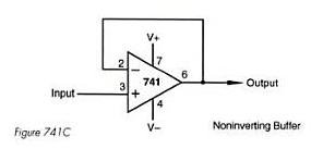
Your opamp configuration is correct as far as it goes. It sounds as though you haven't biased it correctly. Without seeing the circuit details it's hard to advise but pin 3 must be at 0 volts.
The 741 isn't the best choice these days but it will work very well non the less.
VU And PPM Audio Metering
The 741 isn't the best choice these days but it will work very well non the less.
VU And PPM Audio Metering
Hmm. I was using pin 3 as the straight-up, hardwired input from the mp3 audio source. Are you suggesting that I tie pin 3 to ground and try an inverting buffer setup? I'm not opposed to the idea, hopefully I'll have some time this afternoon to give it a go.
As for the use of the UA741, I'm just using it now because I have some sitting around to play with, but I have no problem putting in another order to Digikey before I finish the project. What op-amp would you suggest? (and why?)
Thanks!
-Chad
As for the use of the UA741, I'm just using it now because I have some sitting around to play with, but I have no problem putting in another order to Digikey before I finish the project. What op-amp would you suggest? (and why?)
Thanks!
-Chad
Last edited:
How did you bias pin 3? You did provide bias, didn't you? I am not clear why you are introducing an op-amp anyway. Your earlier mention of diodes suggests you don't quite know what you are doing.
Feed the two signals to your two VU meters. As a separate issue, use a simple resistor pad to combine them into mono (a search on here will show you how to do it - people seem to ask every few weeks).
Feed the two signals to your two VU meters. As a separate issue, use a simple resistor pad to combine them into mono (a search on here will show you how to do it - people seem to ask every few weeks).
This has something to do with the biasing, Boscoe? I think i would like to try using a split supply in future projects, but for this one, ive gotten this far on a single sided supply, so I'd hate to rework the entire design this late in the game.
From what I've gleaned so far, there some significant advantages to using split power (especially in audio applications). So it's something I'm going to need to learn the in's and out's of.
-Chad
From what I've gleaned so far, there some significant advantages to using split power (especially in audio applications). So it's something I'm going to need to learn the in's and out's of.
-Chad
Excellent! One of the marks of a wise man is that he realises the limits of his understanding.scwhitely said:To say I don't know what I'm doing is a bit of an understatement. (I do, however, intend to enroll in some electronics courses next semester). In the meantime, I will look into this biasing and this resistor pad you speak of.
An opamp needs a DC supply to bias each of its inputs. In the case of the unity gain follower, the - input gets its bias from the output. The + input needs to get it from the input, so if there is a coupling capacitor (which would be the normal situation) you need to include a resistor from the + input to a suitable voltage level (could be zero volts in many cases).
Taking your circuit above and lets say it runs on a 9 volt battery.
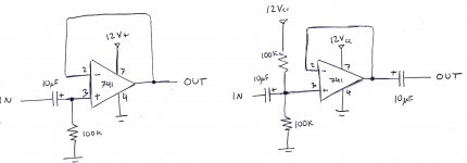
1. You bias pin 3 with two equal value resistors in series across the supply to create a "half supply" reference voltage of 4.5 volts at the junction of the two resistors. Pin 3 connects to that 4.5 volt junction.
100K would be about right. That forces pin 3 to 4.5 volts and the output pin 6 follows suit.
2. You now MUST AC couple both input and output using small capacitors of say 10uf (microfarad). Make sure you get the polarity correct. Plus end of cap to pin 3 and same for pin 6.
Thats it... one opamp buffer.
Hmm, I had time today to give this a try, but I still seem to be doing something wrong, the signal is not showing up at the amplifier. Here are the configurations I tried. I tried both setups with and without the coupling cap on the output. For the record, the power supply is a 12V 3.2Ah SLA, which will end up being the power supply in the finalized project.
-Chad?
-Chad?
Attachments
Another thought in trying to cover all bases... was or is the opamp from a genuine source ? They are so many fake parts around.
In your diagram pins 1 and 8 are (and should be) left floating and pin 6 is the output.
Measuring the DC current taken by the opamp might (might !) help show if there is a problem. It should be around 1 to 2.5 milliamps for the 741 opamp. Worth checking.
As to using an SLA (which I must confess I do all the time for some things), well it's worth staying safe and keeping what you are working on safe. For something like this a 100 ohm resistor in series with the positive supply might be advisable together with a small cap (10 to 100uf) across the "circuit supply end". So that means the caps across pins 4 and 7 on the opamp. The series resistor lets you measure the current too by just measuring the volt drop across it and using ohms law.
Better safe than sorry with SLA's the current capability is in the 100's of amps region.
Yep, you are right. I went back and double checked everything, which seemed to be in order.
However, what was happening was that for some reason, the TPA3110D2 amp chip had gone into shutdown mode when (and each time) I hooked up that battery (woops). After giving the amp a "gentle" reset, the 741 buffer amps (unity gain followers?) worked like a charm. Separate l/r channels for the VU meters, one mono channel for the amp. Beautiful. Thanks again for all your help!
As for the summing of the channels, as of right now I'm just hard wiring them together and it seems to sound pretty good (no thorough testing yet), but it couldn't hurt to look into these resistor pads if that's the correct route.
Once again, thank you so much. In the immortal words of the A-Team's Hannibal; I love it when a plan comes together.
-Chad
Ah ")
Pleased it's all working for you. Yes the buffer is a unity gain amp. Without seeing the full circuit details it's hard to imagine how it's all hooked up but sounds like you are on the right track.
If you need gain from the opamps then that's easy, two resistors and a cap is all that's needed.
Excellent
Thanks for all the input Mooly, I should probably invest in a bona fide power supply for my work station. I've already spent plenty on a nice soldering iron, power-tools, and everything else, whats a little more dough? No pockets in the shroud.
I suppose the fact that my projects are almost exclusively battery powered has lead me toward a false sense of security with them. It probably wouldn't take much more than a minor mishap to change that.
As for the full circuit, I can confidently say it's the most complex project I've worked on to date; involving solar panels, class D amps, VU meters, on-board USB charging (Apple, Inc. didn't make that any easier on me), and now, nod to you, a buffer amp stage. I'm on the home stretch now!
- Status
- This old topic is closed. If you want to reopen this topic, contact a moderator using the "Report Post" button.
- Home
- Source & Line
- Digital Source
- Isolating Left & Right Channels, before mono amplification