Hi all,
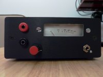
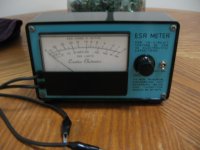
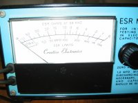
Here is the simple capacitor ESR meter which works very well.
My version of the ESR meter is based mainly on the project published by Lawrence P. Glaister at
Capacitor ESR Tester
There are several modifications though which I think are important:
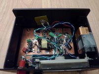
1. I used the impulse step-down transformer to couple the oscillator+driver with the load and to reduce the output impedance. The transformation ratio is about 15:1 but it is not critical (you can use 10:1 for example). What is critical is to adjust gain and bias for Q1 to stay in linear region. I extracted the transformer from old Nokia cell phone SMPS charger.
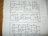
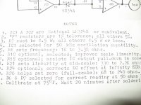
2. I paid particular attention to Q1 amplifier biasing and gain. The key here is that Q1 should stay in the linear region all the time (no clipping). All the voltages are indicated on the circuit diagram.
3. I used higher oscillation frequency. Fo is around 233Khz.
The layout of the circuit is nothing special: ground plane and "ugly construction" (see photos).
Here is the simple capacitor ESR meter which works very well.
My version of the ESR meter is based mainly on the project published by Lawrence P. Glaister at
Capacitor ESR Tester
There are several modifications though which I think are important:
1. I used the impulse step-down transformer to couple the oscillator+driver with the load and to reduce the output impedance. The transformation ratio is about 15:1 but it is not critical (you can use 10:1 for example). What is critical is to adjust gain and bias for Q1 to stay in linear region. I extracted the transformer from old Nokia cell phone SMPS charger.
2. I paid particular attention to Q1 amplifier biasing and gain. The key here is that Q1 should stay in the linear region all the time (no clipping). All the voltages are indicated on the circuit diagram.
3. I used higher oscillation frequency. Fo is around 233Khz.
The layout of the circuit is nothing special: ground plane and "ugly construction" (see photos).
Attachments
Very nice! I have one that is build for fixing Hospital equipments. Take a look of this design.
Great! beautifully done
") . I believe I saw your design on the net and considered it as one of the prototypes.
. I believe I saw your design on the net and considered it as one of the prototypes. Your circuit seems more accurate too, but high accuracy was not my goal here. I was also concerned with the usage of the op-amps for amplification at high frequencies (that's why you need three in series to achieve required gain).
cool!
Actually, it is not an ESR meter, it is a simple (scalar) impedance meter.Hi all,
Here is the simple capacitor ESR meter which works very well.
The only case it could display the esr is when the capacitor's self resonance frequency happens to coincide with the measurement frequency.
That said, it is certainly a useful piece of gear anyway.
Actually, it is not an ESR meter, it is a simple (scalar) impedance meter.
Agreed.
Do you have this in files with pcb or .LAY file?
I've tried to build this one someone modified to use a 9 volt battery and LED, but didn't have a 25K pot, I have Liner 5K, 10K and 15K Pots. or I didn't have the high voltage CAP for voltage protection.
So I'm thinking that might have caused it not to work. With the few I've tried to build, I could have bought two or three of the blues already, but it kind of takes the fun out of trying to DIY.
Thanks
Bob
Very nice! I have one that is build for fixing Hospital equipments. Take a look of this design.
When I tried the link http://circuitcellar.com/microchip2007/winners/third.html it gave an error "Page Not Found".
I tried the Hung kit. When the unit stopped reading ESR after 6 month's he said it was a solder joint. (After 6 month's.) Even sent photo's of the board to him, even gave it to a Computer Electronics class I was taking until funding was canceled so they could work with it and they all said it was the software. All solder joints were perfect. They put a scope on it and only the PIC was not working for ESR reading. So in order to fix the kit I would have to order the chip again since his program is propitiatory.
I'm not a designer, still trying to learn electronics, building test equipment was one way to try and save money. Trying to build the ESR meters have been the most difficult. All the other test equipment I build has been fine. Transistor/Diode tester, Old Oscilloscope from McGraw Hill, Dual Regulated Bench power supply, Signal Generator, Logic Probe, etc. have all worked first try. Just can't seem to build a workable ESR meter.
It's been said some have used their own program on the Hung kit, but I have never been able to find anyone that really has that has offered it on open source or I'd give it a try.
Mailing cost is high out of US. Cheaper inbound for some reason. $11.50 to mail the chip out because it has to go in a small box or padded envelope. Label has to fit on one side.
He said had to purchase a new one since it sounds like the chip was bad. I had someone interested in it since I wasn't in class anymore and then the ESR didn't work when I was showing them how it worked.
After all that I gave up on him. Decided if I could not find the parts/software easy enough it will not get built. He had parts on there that were not available here in the US or were very expensive to order from out of the country.
That one is in a dead box now because the class took it apart. They found other things with it. The board traces would suck up when desoldering with vacuum. He said they were professionally done for him but were not through hole and the traces were not coated like professional ones I've seen.
I've done well etching my PCB's for my other test equipment I made as long as it's in .LAY since I use the negative dry film and have to invert the image for print. Cheaper than buying the positive PCB w/resist.
I just can't figure out why I can't get an ESR meter to work. Must have something to do with trying to build the digital ones not having the exact same part because some of them are very expensive in the states for just hobby or not the exact number. I have to find my parts on boards I've collected. Not able to buy much of anything right now. Sometimes the author of one would tell me something else would work in place. Found one that had a 7805 in backwards on his PCB and schematics after it was built so that one is in the dead box also. I can't edit the files. I don't know enough to do that or buy the software to learn.
But now a friend gave me their 42" LCD TV that doesn't work and I'm needing an ESR meter again. It's cheaper to buy them now than repair them. 42" LCD $350-$450 at Costco.
Return the original ATMEGA to Le Hung, you will probably will get a new copy.
I agree that this meter could be troublesome mostly due to the (very) critical 4093.
There is another discussion of that project at the "Mig Developments" web site < http://www.migdevelopments.com/search/label/LCR Meter >. Schematic and software files seem to be available from < ftp://ftp.circuitcellar.com/pub/Circuit_Cellar/2008/214/Rusch-214.zip >.When I tried the link http://circuitcellar.com/microchip2007/winners/third.html it gave an error "Page Not Found".
Dale
Thanks, but I'm more interested in the ESR meter.
There is another discussion of that project at the "Mig Developments" web site < MigDevelopments: LCR Meter >. Schematic and software files seem to be available from < ftp://ftp.circuitcellar.com/pub/Circuit_Cellar/2008/214/Rusch-214.zip >.
Dale
Here is another example. Probably too luxurious for your purpose, it is a full vector meter, but at least, it's proven and tested:Thanks, but I'm more interested in the ESR meter.
http://www.diyaudio.com/forums/parts/199046-oldies-but-goodies.html#post2755992
Just a bit beyond. Thanks
Here is another example. Probably too luxurious for your purpose, it is a full vector meter, but at least, it's proven and tested:
http://www.diyaudio.com/forums/parts/199046-oldies-but-goodies.html#post2755992
Really, really simple ESR meter
I've built this ESR meter and had good luck with it. Equivalent Series Resistance Meter
Curt
I've built this ESR meter and had good luck with it. Equivalent Series Resistance Meter
Curt
A more complex ESR meter
A few years ago, I built a uP-controlled capacitance/ESR meter that uses the following principle of operation:
 [/url][/IMG]
The cap measurement uses a steady current source, and measures the time for the unknown cap to charge to a specified voltage. The computation of capacitance is trivial if you know the size of the current, the voltage differential, and the elapsed time.
That same hardware can be extended pretty easily to measure ESR. In this case, the current is not steady, but rather pulsed. The pulse of current causes a voltage to be developed across the series resistance, and also causes the capacitor voltage to rise by the amount of charge in the pulse.
If the current pulse is narrow enough, the cap doesn't get much charge and thus its voltage doesn't move much. So most of the voltage measure across the cap **during the pulse interval** is due to the series resistance. If that voltage is captured in a sample-and-hold, it can be measured, and the ESR calculated by dividing the sampled voltage by the current pulse amplitude.
This approach to ESR measurement is credited to Bob Parker. Dick Smith Electronics in Australia commercialized his design. A writeup was done by Silicon Chip Magazine in the March/April 2004 issue.
My implementation of the analog circuitry is shown below.
 [/url][/IMG]
A uP is needed to switch the current sources on and off, to time the capacitance ramps, to strobe the sample-and-hold, to measure the sample voltage, and to display the results. I used a development board from Renesas that I had floating around. It was plugged into J1 in the diagram above.
--
Curt
A few years ago, I built a uP-controlled capacitance/ESR meter that uses the following principle of operation:
The cap measurement uses a steady current source, and measures the time for the unknown cap to charge to a specified voltage. The computation of capacitance is trivial if you know the size of the current, the voltage differential, and the elapsed time.
That same hardware can be extended pretty easily to measure ESR. In this case, the current is not steady, but rather pulsed. The pulse of current causes a voltage to be developed across the series resistance, and also causes the capacitor voltage to rise by the amount of charge in the pulse.
If the current pulse is narrow enough, the cap doesn't get much charge and thus its voltage doesn't move much. So most of the voltage measure across the cap **during the pulse interval** is due to the series resistance. If that voltage is captured in a sample-and-hold, it can be measured, and the ESR calculated by dividing the sampled voltage by the current pulse amplitude.
This approach to ESR measurement is credited to Bob Parker. Dick Smith Electronics in Australia commercialized his design. A writeup was done by Silicon Chip Magazine in the March/April 2004 issue.
My implementation of the analog circuitry is shown below.
A uP is needed to switch the current sources on and off, to time the capacitance ramps, to strobe the sample-and-hold, to measure the sample voltage, and to display the results. I used a development board from Renesas that I had floating around. It was plugged into J1 in the diagram above.
--
Curt
I looked at that one. I had no idea how to do what he mentioned. He mentioned " I made mine using an Amidon ferrite core, type EA-77-188, which is a tiny double-E core having a cross section of 22mm2, and external dimensions of about 19x16x5mm total. I used the nylon bobbin that Amidon delivers with it, wound a primary winding consisting of 400 turns of AWG #36 wire, and as secondary I wound 20 turns of AWG #26 wire. If you have a larger or smaller core, you can adjust the turn numbers in inverse proportion to the cross section area. The wire size isn't critical - the gauges I used are about 3 or 4 numbers thicker than necessary".
- Status
- This old topic is closed. If you want to reopen this topic, contact a moderator using the "Report Post" button.
- Home
- Design & Build
- Equipment & Tools
- Simple Capacitor ESR meter