Im building a Dual mono DAC around the BB PCM1794, which gives out the balanced output. How do I convert the balance to single ended. I want the DAC to be able to output both SE and balanced.
So.... to make the blanaced output SE I guess I take the output from the DAC chip after the I/V into a converter such as INA134 to SE phono connectors. Then at the same time take the balanced output of the I/V to XLR's for balanced output?
Also how do you make a fully balanced active xover or is that asking for trouble. Do you just build twice what you would normally build, put the +into one half and the -into the second then use the INA at the end of it.??
Cheers Matt.
Balanced I/V should not be a problem, there discrete (passlabs D1 I/V stage) or op-amp solutions (for ex. the I/V of the AD1955 eval board uses ad797 op amps).
You take the balanced out (+ and -) or the se (+ and GND).
As far as xovers I don't know anything about it, if I had to guess it sounds like component tolerance may be a problem in building identical differential filters, maybe not. Professional equipment uses lots of balanced but they may convert back and forth as needed.
In my system I like balanced so much so I keep mine from the dac to the speakers and don't do active filtering.")
You take the balanced out (+ and -) or the se (+ and GND).
As far as xovers I don't know anything about it, if I had to guess it sounds like component tolerance may be a problem in building identical differential filters, maybe not. Professional equipment uses lots of balanced but they may convert back and forth as needed.
In my system I like balanced so much so I keep mine from the dac to the speakers and don't do active filtering.
OK so after the output of the DAC I have it balanced so there is the + and -. For balanced I take all of it and for SE only I use the + and grnd. So I get the 129 SNR for SE and 132 for balanced. If I use the INA do I maintain the 132 or does the chip basically just short one output to ground.
If I want to take balanced from the DAC to the SE active xover I guess I will then need the INA in the xover.
If I want to take balanced from the DAC to the SE active xover I guess I will then need the INA in the xover.
If you actively convert balanced to SE via electronics or transformer you preserve the S/N of the balanced signal...if your converter has a S/N that high!
I suspect the usual method of doing balanced xovers is balun conversion at the ins/outs, but I did exactly what you described (double the circuit) with my recent crossover. The tradeoff is lower distortion/noise versus loss of CMRR, I believe. Higher component cost too, of course.
I suspect the usual method of doing balanced xovers is balun conversion at the ins/outs, but I did exactly what you described (double the circuit) with my recent crossover. The tradeoff is lower distortion/noise versus loss of CMRR, I believe. Higher component cost too, of course.
OK cheers maybe ill try balanced with cheap ops to see what its like. Im doing a three way which will require quite a few as it is so doubling that would cost much more. I dont think that TI Nsemi and AD waill supply that many free samples
Im going to try and get 8opa627's for the 1st I/V section got the DAC as well as four surface mount 28pin things and another 8pin DIL.
Maybe if I can get loads of ops ill build it balanced but until then, its time to find a converter with a 132 SNR!
Im going to try and get 8opa627's for the 1st I/V section got the DAC as well as four surface mount 28pin things and another 8pin DIL.
Maybe if I can get loads of ops ill build it balanced but until then, its time to find a converter with a 132 SNR!
5th element said:OK so after the output of the DAC I have it balanced so there is the + and -. For balanced I take all of it and for SE only I use the + and grnd.
If you take signal from - and gnd you will have inverted polarity audio.
Selecting + or - at the dac will give you absolute polarity control.
Eric.
I've just thought of something that could present a bit of a problem unless there are ways of getting round this.
How do you adjust the volume of two channel balanced with a single 2 track pot??? The only thing I can think of is convert the balanced to SE then put the pot in the signal path then convert the SE to balanced again, this seems a little bit over the top and im sure there are much better ways of doing this.
How do you adjust the volume of two channel balanced with a single 2 track pot??? The only thing I can think of is convert the balanced to SE then put the pot in the signal path then convert the SE to balanced again, this seems a little bit over the top and im sure there are much better ways of doing this.

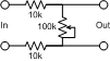
Spot on, except the arrow doesn't connect to ground. Think of it like this:
The pot just shorts the output when at zero volume. You can use just about any values you like/have, but if the pot has a value close to the input resistors the circuit will attenuate the signal quite a bit, even at max. I'd recommend at least a 1:10 ratio.
Rune
The pot just shorts the output when at zero volume. You can use just about any values you like/have, but if the pot has a value close to the input resistors the circuit will attenuate the signal quite a bit, even at max. I'd recommend at least a 1:10 ratio.
Rune
Attachments
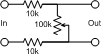
Come to think of it how does that work?
If you have it so the pot is to the left or up on your diagram then the upper input is connected to ground and the bottom is at the equivelent of full volume. The move the pot to the other end of the track and its visa versa bottom input to ground and top at full volume
Could you explain to me how if at all this works
cheers Matt
There is no connection to ground. When the wiper is at the top, the output is effectively shorted out. As the wiper moves farther away from the top, you have a voltage divider, where the the output voltage will be Vin * Rx / (Rx + 10k + 10k); Rx being the resistance of the potentiometer in it's actual position.
Given ideal output from the driving amp,put and an ideal input in the driven amp, you could ommit one of the fixed resisitors, but I wouldn't trust those assumptions
Rune
Given ideal output from the driving amp,put and an ideal input in the driven amp, you could ommit one of the fixed resisitors, but I wouldn't trust those assumptions
Rune
Ok cheers looks like we were both posting at the same time and you answered my questions as I was asking them.
Ironically what you 1st described looks like a balance attenuator as in it will fade between left and right channels if connected SE. And then the 2nd a balanced attenuator
Cheers again Matt
Ironically what you 1st described looks like a balance attenuator as in it will fade between left and right channels if connected SE. And then the 2nd a balanced attenuator
Cheers again Matt
Well, I'm still under moderation, so chronology gets a tad confusing.
Still, the first schematic and the second are functionally identical.
The first would only become a balance control if you connect the wiper to ground and feed it two single ended channels.
But as I wrote: there is no ground connected to anything. That's pretty much what balanced is about in the first place.
Rune
Edit: I'm no longer under moderation: Whoopee!
- Status
- This old topic is closed. If you want to reopen this topic, contact a moderator using the "Report Post" button.
- Home
- Amplifiers
- Solid State
- Balanced to SE