Hello,
I am collecting information aboit UcD class d amp for subwoofer and need your help,
because it is a new area for me.
Here it is the requirements for the project:
1. It is UcD type class d amp.
2. uses full h-bridge - 2 x IR2110 + 4 x IRFB4227 + 2 x T200-2 as output filter.
3. Single supply +50 V !! ( transformer is allready in my hand !!") )
)
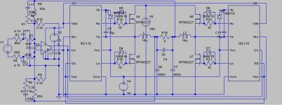
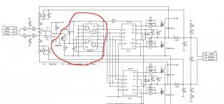
I want to build my amp as PIC1.jpg .....
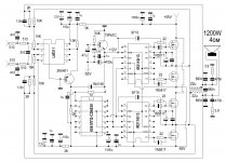
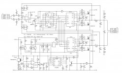
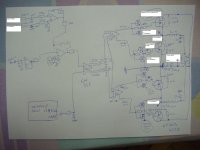
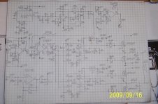
But found some similar schematics PIC2.jpg and PIC3.jpg ....with more components on it ..
So my questions are:
1. Is it a PIC1.jpg working amp ( if I build it with all components and proper PCB )
or just shematic for simulation in LT Space ?? With other words
- is it possible to make UcD amp only with LT1016 + 2 x IR2110 + 4 x IRFB4227 ?? Or I need
in additional 1/2 transistors and CD4030 as shown on PIC2 and PIC3 ??
2. Can I use LM311 instead of LT1016 for subwoofer UcD amp ??
3. Can I use IRF540N Instead of IRFB4227 for this amp for 200-300 W power and 8 ohm load ??
with IR2110 ??
When I clear my conception will publish shematics and PCB for your approval ...
Thank you in advanse for all of you, with helpful answers,
Emil
I am collecting information aboit UcD class d amp for subwoofer and need your help,
because it is a new area for me.
Here it is the requirements for the project:
1. It is UcD type class d amp.
2. uses full h-bridge - 2 x IR2110 + 4 x IRFB4227 + 2 x T200-2 as output filter.
3. Single supply +50 V !! ( transformer is allready in my hand !!
)I want to build my amp as PIC1.jpg .....
But found some similar schematics PIC2.jpg and PIC3.jpg ....with more components on it
..So my questions are:
1. Is it a PIC1.jpg working amp ( if I build it with all components and proper PCB )
or just shematic for simulation in LT Space ?? With other words
- is it possible to make UcD amp only with LT1016 + 2 x IR2110 + 4 x IRFB4227 ?? Or I need
in additional 1/2 transistors and CD4030 as shown on PIC2 and PIC3 ??
2. Can I use LM311 instead of LT1016 for subwoofer UcD amp ??
3. Can I use IRF540N Instead of IRFB4227 for this amp for 200-300 W power and 8 ohm load ??
with IR2110 ??
When I clear my conception will publish shematics and PCB for your approval ...
Thank you in advanse for all of you, with helpful answers,
Emil
Attachments
Last edited:
Vdd=50V is only less then 150W on 8 ohms.
PIC1 is only simulation, but very close to something usable, however the lack of overcurrent protection makes me not to like it.
T200-2 is gigantic, 1 peace is more than enough for 1 kW.
IRF540N is OK, but...
For single supply amp at this power level, Texas Instruments has excellent integrated solutions, with built-in overcurrent protection, etc...
Thank you !
Hello Pafi,
1. 150 W on 8 ohm with +50 V - OK. I need quality ... and 150 W i OK !!
2. ... What I have to add to PIC1.jpg ( from first post ) to make it a real project - all in RED from PIC5.jpg ??!! Is it GOOD or BAD to use examples from PIC2 and PIC3 for my design ?? If not good - what I have to add between LT1016 ( LM311 ) and IR2110 ....
3. T200-2 - I have them 'on stock' .... it is not a problem as usage and money
4. "IRF540N is OK, but..." - can I use it ??
Best Regards,
Emil
Attachments
Let me answer instead of Pafi, after you sent me a private to help.
1. Don't get upset but you like a beginnner. so if your supply is planned to be 50V, use the TAS5630, you won't get more power or better quality from 50V than that, without a much better understanding.
2. you need to add dead-time adjustment (van be done mith an RD network befora IR2110, or some other sofisticated way), you should add overcurrent protection, either using shunt resistors, FET Rdson sensing or whatever you want and can do.
3. T200-2 will be huge. If you have so much on stock, then I would make some business, and swap them for T106-2 ones.
4. For testing IRF540N, but if you "want quality" as you mentioned before, then get at least IRF540Z or some better.
For your earlier questions (which are quite trivial)
You can not use Lm311 insted of LT1016, beacuase it lacks complementary outputs.
For 50V you SHOULD NOT use 200V FETs unless you wnat lots of loss, use 100V fets or some more matching your bus voltage.
If you are a beginner, then don't stick to your bad decisions (mostly if others point it out to you, that they are bad), and don't stick to your stock. Do the simplest solution: TAS5630.
I suggest the same as Loryalci.
Being that you are a novice in this field I should go with IC designs and later move on to non bridge designs like http://www.diyaudio.com/forums/class-d/166214-ucd-25-watts-1200-watts-using-2-mosfets.html
I do not make ovp and over current protections in my simulations because it takes more to simulate.
regards,
savu
Hello ..
Pafi, Lorylaci, Savu, DjLeco,
Thank you for your answers.
But let me to continue to ask you about my project...
TAS5630 with RL = 8 ?, 10% THD+N at 150 W is not my class d amp !
Also I don't want to use +/- XX Vdc or "ucd 25 watts to 1200 watts using 2 mosfets" or "simple AB class amplifier" ...
Kindly ask you to help me to build class d amp as I requested and not direct me to other ways, designs ..... etc .....
My new questions:
1. Is it possible to build UcD, full h-bridge amp, single supply +50V with THD+N less than 1 % ??
2. Is it PIC6 and PIC7 a good design for full h-bridge UcD amp ?? Is it optimal and with all necessary components ?? If not - can you send a good input stage schematics ( link to it .. ) for full h-bridge UcD amp .... as example !!!
3. Can you recommend me good mosfet transistors for +50V Ucd -
IRF540Z for 100V ??, IRFB4212 (100V) ??? or which one ???
http://www.diyaudio.com/forums/class-d/204355-level-shifting-half-brige-2.html
4. Can I use one T200-2 with two windings in my design ?? I saw such usage in HIP4080 design .... ???
If you approve PIC6 and PIC7 as good and quality design .. I will draw the schematics in Kicad to see it better and to proceed further ...
Regards,
Emil
Attachments
Pafi, Lorylaci, Savu, DjLeco,
Thank you for your answers.
But let me to continue to ask you about my project...
TAS5630 with RL = 8 ?, 10% THD+N at 150 W is not my class d amp !
Also I don't want to use +/- XX Vdc or "ucd 25 watts to 1200 watts using 2 mosfets" or "simple AB class amplifier" ...
Kindly ask you to help me to build class d amp as I requested and not direct me to other ways, designs ..... etc .....
My new questions:
1. Is it possible to build UcD, full h-bridge amp, single supply +50V with THD+N less than 1 % ??
2. Is it PIC6 and PIC7 a good design for full h-bridge UcD amp ?? Is it optimal and with all necessary components ?? If not - can you send a good input stage schematics ( link to it .. ) for full h-bridge UcD amp .... as example !!!
3. Can you recommend me good mosfet transistors for +50V Ucd -
IRF540Z for 100V ??, IRFB4212 (100V) ??? or which one ???
http://www.diyaudio.com/forums/class-d/204355-level-shifting-half-brige-2.html
4. Can I use one T200-2 with two windings in my design ?? I saw such usage in HIP4080 design .... ???
If you approve PIC6 and PIC7 as good and quality design .. I will draw the schematics in Kicad to see it better and to proceed further ...
Regards,
Emil
1. From 50V supply you won't get more! (modulation error limits the output, so Class-D amp can usually get a bit less out form the same supply as ClasssB) Please use your mind a bit, and at least understand the answers of others, who are more experienced than you.
2. Both PIC 6 and PIC 7 has slow switching freqs, and if I am right no feedback. So it wont be "quality" (really wont be). Do a search for full-bridge single supply UcD, here is a good topic: http://www.diyaudio.com/forums/class-d/132081-single-supply-bridge-ucd-referencing-signals.html
3. I have reccomended one already: IRF540Z, it is quite good, cheap, easy to get. I cannot reccomend easily others, while it depeneds on you what you can get in your country / region.
4. Maybe you can, there is a post about that, read the comments. I have always used two spearate inductors, so I cannot give much more advices, maybe others can.
Don't get it wrong, but you seems like more and more demanding, without seeming to try to understand our answers. Please read some application notes, some literature about Class-D. Otherwise you will just stick the dog to the pole. (don't know the english for that sentence)
PIC6 and PIC7 are quite outdated and bad designs.
progress up to now ...
Hello All,
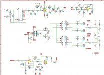
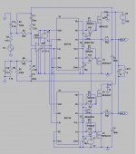
Please find attached latest schematic.
I need your remarks, corrections, suggestions ... etc. about everything EXCEPT power stage - IR2110+IRFP4227 - it is not ready and will be improved!
Please correct schematics, C and R values .... ...etc ...
Remember that this is only SUB amp - up to 200-300 Hz !!!!
Can you help men with correct values for : D5, D6, R7, R8, C6 and C7 ??
Regards,
Emil
Hello All,
Please find attached latest schematic.
I need your remarks, corrections, suggestions ... etc. about everything EXCEPT power stage - IR2110+IRFP4227 - it is not ready and will be improved!
Please correct schematics, C and R values .... ...etc ...
Remember that this is only SUB amp - up to 200-300 Hz !!!!
Can you help men with correct values for : D5, D6, R7, R8, C6 and C7 ??
Regards,
Emil
Attachments
Hello All,
Please find attached latest schematic.
I need your remarks, corrections, suggestions ... etc. about everything EXCEPT power stage - IR2110+IRFP4227 - it is not ready and will be improved!
Please correct schematics, C and R values .... ...etc ...
Remember that this is only SUB amp - up to 200-300 Hz !!!!
Can you help men with correct values for : D5, D6, R7, R8, C6 and C7 ??
Regards,
Emil
The questioned values are usually determined by experimentation or simulation. But here is a quess calculation:
Charge time constant of capacitor tau_charge=(R7+Rout)*C6
Discrage time constant of capacitor tau_discharge=(Rout)*C6
where Rout is the output impedance of the comparator.
The approximate dead time is the difference between this two time constant: delta-tau=R6*C6
This is an approximate only, the dead-time valuse should be experimented. Increasing dead-time decreases the idele current (due to cross-conduction), but also increases THD. There is usually an optimum dead-time value, where THD is small, and losses also small, because the antiparralel diode loss minimalization.
Keep in mind that IR2110 has a serious issue when driving with short pulses. Since you are using a fast comparator (this is good of course, but), you may encounter problems. Th RCD network may help you with this, not only with dead-time.
Hello,
Hi,
My load is 8 ohm ... But you may post your answer for 4 and 2 ohm - if someone want's to use this values ...and test the project ....
Please correct everything except power stage .... I have to add current limiting .... protection .... so schematic is not complete in this part ..
Regards,
Emil
Hi,
My load is 8 ohm ... But you may post your answer for 4 and 2 ohm - if someone want's to use this values ...and test the project ....
Please correct everything except power stage .... I have to add current limiting .... protection .... so schematic is not complete in this part ..
Regards,
Emil
Hi,
My load is 8 ohm ... But you may post your answer for 4 and 2 ohm - if someone want's to use this values ...and test the project ....
Please correct everything except power stage .... I have to add current limiting .... protection .... so schematic is not complete in this part ..
Regards,
Emil
If you are a beginner, first design only the amp, without everything else. You will be happy if only the amp works. The schemtic is the easier part, the layout is much harder way to go.
So 8 ohm, 50V full bridge, I still reccomend TAS5630. Or for bigger supply voltages here is an idea you can start on:
An externally hosted image should be here but it was not working when we last tested it.
An externally hosted image should be here but it was not working when we last tested it.
Hi
I don't want to build TAS5630 amp ... THD+H = 10 % - I am beginner in class d, but not deaf !!
I want go as I requested .... not with HIP4080 ... or similar ways ...
Can you help with suggestions for LM361 --> 2 x IR2110 --> MOS --> T200-2 .... ??
That is what I need help.....
Regards,
Emil
I don't want to build TAS5630 amp ...
THD+H = 10 % - I am beginner in class d, but not deaf !! I want go as I requested .... not with HIP4080 ... or similar ways ...
Can you help with suggestions for LM361 --> 2 x IR2110 --> MOS --> T200-2 .... ??
That is what I need help.....
Regards,
Emil
I don't want to build TAS5630 amp ...
I want go as I requested .... not with HIP4080 ... or similar ways ...
Can you help with suggestions for LM361 --> 2 x IR2110 --> MOS --> T200-2 .... ??
That is what I need help.....
Regards,
Emil
TAS5630 has a THD of 0,03% at medium power (1-50W). 10% is for 150W at 8 Ohm from 50V supply. At 120W it is 1%, and at 100W it is 0,1%.
First of all you must decide what you want!
You said 8 ohm and 50V single supply. But what THD levels and complexity you choose? What is your planned switching frequeny? Do you want fixed frequency PWM, hystereis or UcD self-oscillation. Since in the topic you said UcD, but your latest schematic is a hysteresis oscillation amp.
From 50V supply you cannot get really more than 100W at 0,1% THD, because of the modulation limit. Because IR2110 has limited pulse width, it really limits modulation. For 50V, you also should not use a 600V driver.
Hi
Thank you !
That is answer that I am waiting for .. !
The power that I have is 50-56 V - single supply .... I don't want to change it .. so let me to use it ....
Second I have 8 Ohm load ... BUT it can be 4 Ohm .... Is it better for schematics .... ???
Please forget about TAS5630 for now .... please .....
"From 50V supply you cannot get really more than 100W at 0,1% THD"
- if we speak only about SUB amp - 0-300 Hz - how much is the possible MIN THD ??
"Do you want fixed frequency PWM, hystereis or UcD self-oscillation" - which kind ( topology ) of this amps can do less THD with 50V + 4/8 Ohm load ??
"For 50V, you also should not use a 600V driver" - please suggest me driver ...
Regards,
Emil
THD levels below 0,1% is pretty hard with Class-D, need a lot of optimalization. It is not really frequency dependent! It is mainly limited by the supply and the modulation. What don't you understand in it?
Which topology will have less THD? I cannot tell, because it depends heavily on lot of other factors. (supply voltage, load, dead-time setting, feedback, driving network) UcD is usually the simplest, and gives low THD levels, but as I said THD can be high with unproper dead-time selection and others. Ucd has a con: limited loop gain.
Fixed freq PWM has a great pro with fixed freq, which you can syncrhonize to other channels and/or to power supply (reduced interferrence). Also gain can be easily changed. Hysteresis oscillation has less frequency change, but it is pre LC feedback, so its cons comes from it.
TI has a lot of 120V drivers UCC27xx series. Intersil has HIP4081 (which is a full-bridge driver only, no comparator). But using HIP4080 with integarated high-speed comparator can raise your modulation limit. HIP2100 is half-bridge driver of Intersil. IRF has IR2010 which much faster than IR2110 (don't know if has the same minimal pulse width error as IR2110).
You can also use a discrete gate drive.
Try Something like this
Hi Savu
hello just some tips i need to know before i start this project
1 will single PCB be good enough for this amp as i have little experience in designing ds pcb
2 can IRFP 250 N be used for experimental purpose once amp working irfb4227 will
be used
3 ultra fast ic LT1711 ANY substitutes this ic hard to get in my city
savu with little help from you i think i can suceed in my project
thanking you
sameer x1
- Status
- This old topic is closed. If you want to reopen this topic, contact a moderator using the "Report Post" button.
- Home
- Amplifiers
- Class D
- UcD project, Subwoofer class d amp, full h-bridge, single supply +50 V