I started this a while back. I have all of the physical construction done, everything is mounted to the chassis. I am doing everything on PCBs so things are going slowly one step at a time. Supplies are all to be regulated and bias is to be controlled by circuits inspired by some Broskie posts. Should require little to no adjustments. Should be a pretty complex/fun project. Output transformers are PAT1070UC.
Anyway, I thought I would throw my basic circuit up and let you guys throw rocks at it. Don't hold back.
Anyway, I thought I would throw my basic circuit up and let you guys throw rocks at it. Don't hold back.
Attachments
Nobody? I guess I'm mostly looking for feedback on dropping screen voltage through the Zeners. Anybody ever tried anything like that? Should I bypass the zeners with caps?
These output transformers are about 6.4k:8 impedance ratio, so if I kept screens at 450V (which the basic McIntosh circuit would do) the load line would cross way below the knee of the pentode curves. I was afraid this would be hard on the screen if this thing were overdriven. Options for dropping the screen supply are limited in this output configuration, hence the zeners.
These output transformers are about 6.4k:8 impedance ratio, so if I kept screens at 450V (which the basic McIntosh circuit would do) the load line would cross way below the knee of the pentode curves. I was afraid this would be hard on the screen if this thing were overdriven. Options for dropping the screen supply are limited in this output configuration, hence the zeners.
Cool circuit, but the use of 841 as gain devices seem a bit over kill, but Im sure they'll add some awesomeness to the amp. I've never used zeners in the signal path b/c I assume they add harshness. ") . Since u plan to use regulated supplies, why not for the screens? (remember tho, fixed bias all around begges for reduced tube life).
. Since u plan to use regulated supplies, why not for the screens? (remember tho, fixed bias all around begges for reduced tube life).
Other than those uneducated comments, I think ur design look good. (is global feedback back?)
Edit: I see its triode connected now, so of course now I see ur point in dropping the screen voltage with series zeners. Perhaps a cap in parallel with zener?
. Since u plan to use regulated supplies, why not for the screens? (remember tho, fixed bias all around begges for reduced tube life).Other than those uneducated comments, I think ur design look good. (is global feedback back?)
Edit: I see its triode connected now, so of course now I see ur point in dropping the screen voltage with series zeners. Perhaps a cap in parallel with zener?
Last edited:
Actually, it is not triode connected. It is the old unity-coupled circuit used in all of the McIntosh amps. Screen goes to opposite plate. The strong cathode feedback results in full pentode power with characteristics of a triode with mu=2.
I am very excited about the 841s. It was a requirement for the amp to have a thoriated tungsten filament somewhere. Seriously, it is not easy to find a linear tube that can idle at 400V plate and deliver 200V+ rms volts signal. They will require a little grid current drive, but it as also a requirement that this amp have A2 drive somewhere in it as well.
I think I will put a cap in parallel with the zener. I'm thinking there could be some voltage variation across the zener as tubes cut off and screen current disappears/reappears.
I don't know if global feedback will even necessary for this thing. Open loop damping factor should be better than lots of amps closed loop. I just threw it in there as an option. Should be about 6dB if I calculated correctly.
This should be a fun project. I just got my regulator boards in, and I can't wait to finish this power supply.
I am very excited about the 841s. It was a requirement for the amp to have a thoriated tungsten filament somewhere
. Seriously, it is not easy to find a linear tube that can idle at 400V plate and deliver 200V+ rms volts signal. They will require a little grid current drive, but it as also a requirement that this amp have A2 drive somewhere in it as well.I think I will put a cap in parallel with the zener. I'm thinking there could be some voltage variation across the zener as tubes cut off and screen current disappears/reappears.
I don't know if global feedback will even necessary for this thing. Open loop damping factor should be better than lots of amps closed loop. I just threw it in there as an option. Should be about 6dB if I calculated correctly.
This should be a fun project. I just got my regulator boards in, and I can't wait to finish this power supply.
When there is no screen current there will be no voltage drop across the zener. That's not a big deal since the tube is cut off and is effectively not there. The problem would be as it turns back on (or as it shuts off), there would be some small variation in voltage across the zener. If we assume that it is always best to keep screen voltage constant in a beam tube then we may want to bypass the zener with a cap to decrease these voltage variations.
The question is, how big of a cap do we need? I'll have to think about that a bit.
The question is, how big of a cap do we need? I'll have to think about that a bit.
The screen can be kept free of AC if you wish. Afaik.
You might want to drop a highish value resistor to ground from the screen, keeping the zener alive unless the AC drives the whole side "off"...
The size of the proposed cap will depend on the effective impedance the screen presents, which if drawing current will look fairly low... otoh you do not want a cap that can hold a charge and float the DC high at the wrong time...
I think you might do better with a straight voltage divider to supply a % of the total voltage. Then the question is (again) do you want to drive the screen with AC or not?
_-_-bear
_-_-bear
Ah, I see now, was using my iphone last night and didn't get the whole picture. I agree you should ensure the zener never cuts off, and a resistor to negative voltage rail may help.
Looking at the voltage swings on plates and screens I am a little puzzled this doesnt destroy the tube...Lets say you are close to max and swing 350volts on the plates. If mu is 2 you swing 175volts on the grids. So V7 has almost -200v on grid, -100v on screen, and +800v on plate. No harm here, it is completely shut off. V9 has +150v on grid, +600v on screen, and +150v on plate. Wont the screen current in V9 be a tad high?
Interesting connection tho, I need to ponder this.
If no global NFB are u going to include local feedback (cathode resistance)? Gain will be a little much as is? Perhaps go from 6SN7 to a lower gain DHT on the input as well?
You might want to drop a highish value resistor to ground from the screen, keeping the zener alive unless the AC drives the whole side "off"...
I think you might do better with a straight voltage divider to supply a % of the total voltage. Then the question is (again) do you want to drive the screen with AC or not?
I assume you mean to the cathode rather than to ground. That sounds like a good idea, much better than a parallel cap alone.
I do not want to drive the screen with AC. I want it to be at a constant voltage with respect to the cathode. There is already strong feedback to the control grid. I don't think more is necessary, especially on an insensitive grid like the screen.
I'm thinking if I drive the screen from a divider it would need to be somewhat low impedance and wasteful of power. I think the zener will provide a much lower impedance at low currents.
Looking at the voltage swings on plates and screens I am a little puzzled this doesnt destroy the tube...Lets say you are close to max and swing 350volts on the plates. If mu is 2 you swing 175volts on the grids. So V7 has almost -200v on grid, -100v on screen, and +800v on plate. No harm here, it is completely shut off. V9 has +150v on grid, +600v on screen, and +150v on plate. Wont the screen current in V9 be a tad high?
If no global NFB are u going to include local feedback (cathode resistance)? Gain will be a little much as is? Perhaps go from 6SN7 to a lower gain DHT on the input as well?
The low mu comes from the cathode windings. When you swing +150V on the grid the grid is still negative with respect to the cathode.
It is a really cool circuit and is very linear but the price you pay is you have to deliver a ton of voltage drive.
Sensitivity will be about 1Vrms for this amp.
Please have a look at the MC275 schematic. It uses the same power tubes as yours, running both screens and plates at 450 volts. As this well reputed design doesn't feature zeners for screen supply, I don't see any reason for them.
Kay,
There is a very big difference between this amp and an MC275 and that is the load impedance. Mine is 6.4k and I believe MC275 is just over 2k(very steep load). This was to ensure that the load line went above the knee of the curves(knee is very high due to high screen voltage). This is very important in pentodes/beam tubes. I did some quick eyeballing on a 6550 datasheet and you get around a fourfold increase in peak screen current when you load below the knee. This is a very old rule of thumb to load pentodes above the knee of the curves. I promise I am not trying to be 'too clever' here. It really would be hard on the screens if this amp were driven hard with this load impedance.
McIntosh knew what they were doing when they chose their load impedance. I get the feeling that Van der Veen overlooked this when he designed these transformers judging by the email response I got from him...
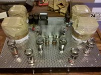
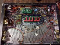
Here are pictures of the progress that I have made so far.
I have finished the mechanical stuff and all power supplies. That's probably 90% of the work.
I am going to do this all on PCBs and will be ordering far in excess of what I need (since it hardly changes the price I might as well) so if anything I build looks like it would be useful to you just PM me and I'll sell any of them at cost. So far I have just done the Maida regulator PCB and there are 28 left.
Next up, I'll be having a board fab'd that will contain source follower driver/output tube.
Attachments
I'm a bit newb with unity-coupled configuration, but as I'm starting to restore one, I'll ask the question. Why not use a resistor feed (instead of zener), and a capacitor from OT side of resistor to cathode - my 100W amp uses 2uF and 4k7 with 6L6GC. If a zener really was needed then it could go across the cap for regulation.
Ciao, Tim
Ciao, Tim
Last edited:
Tim,
As you probably already know, this output circuit keeps voltage constant between screen and cathode(thus acts as a pentode) and is typically run with screen voltage equal to the idle plate voltage.
My goal was to lower screen voltage to 250V(Vg-k, not wrt ground) or so in an efficient manner and provide a stiff supply. It is as efficient as possible and pretty stiff. The only thing to worry about is what happens as the tube cuts off. I would expect there will be some voltage fluctuation as screen current gets real low since we are rounding the knee of the curve for the zener diode. Will it matter? The tube is near cutoff anyway and isn't contributing a whole lot to the amp output at that point. I can put a resister between screen and cathode to give the zener a minimum current so we never round the knee. I may have to take some measurements in a few configurations and see if it really makes any difference or if I'm worrying about nothing. Thanks for the suggestion.
I have attached another schematic which is the circuit I plan on trying on the first cut.
Attachments
I have attached another schematic which is the circuit I plan on trying on the first cut.
Add 2.4 ohm to balance the cathode windings
OK I'm with you now - thanx. What would be the problem with fitting a capacitor between zener and cathode, to maintain a low impedance voltage source during cut-off, and possibly lower and stabilise the effective source voltage impedance during screen current variation as saturation is approached.
Now I vaguely think I appreciate why my amp has a 2uF between cathode and screen (opposite anode) - given that I reckon the OT doesn't use bifilar windings, and so the leakage inductance influence is possibly somewhat countered by the cap.
Now I vaguely think I appreciate why my amp has a 2uF between cathode and screen (opposite anode) - given that I reckon the OT doesn't use bifilar windings, and so the leakage inductance influence is possibly somewhat countered by the cap.
- Status
- This old topic is closed. If you want to reopen this topic, contact a moderator using the "Report Post" button.
- Home
- Amplifiers
- Tubes / Valves
- Unity-Coupled amp project