Hi all,
not a complete newbie but might as well be given my abilities..Following an inadvertant slip with a scope probe I have apparently fried my 1798 DAC. Don't laugh but I was putting a valve output stage onto it (audiophool at heart), the slip was the relevant problem rather than the tube stage which works....Weird buzzing is all I can get now. It sounded pretty damn good before. I think the probe went over the 1,2,3 pins, but wasn't looking so can't be sure. Anyway I'm thinking could I buy another DAC chip, soler it in (SMD) and get away with it or might I have I shagged the whole shebang?
Also can a person of my feeble abilities work out the above (with help natch)? Or would I be better getting a new DAC kit and save the heartache given it has a solid PSU and tweaked bits n bobs, and if so what can you recommend that will sound really good that a feeb like me might be able to build/mod?
Thank you in advance, and being in UK I'm off to bed so apologies if the reply doesn't arrive 'till tomorrow.
I don't see how you could have damaged anything if you are sure about which pins you may have shorted. Pins 1 thru 7 are all inputs for data, clock & mode selections, and are all rated to handle either B+ or grounding, and shorting any of them together should not have caused any harm. Even if it did, it is extremely unlikely to cause buzz as a symptom. I think you must have either shorted different pins than you think, or have a purely coincidental, unrelated problem.
Valves... so could you have shorted or connected anything that was charged up (even a floating coupling cap) to the DAC/or PCB as that could zap it.
Scope probe and scope... if that was used AC coupled to measure a high voltage then the input coupling cap in the scope is charged to that voltage. Touch it to a sensitive IC next and that cap discharges into that IC. Always touch the probe to ground before making a new measurement if in doubt.
Whatever has happened, normal faultfinding now kicks in... check supplies, scope the supplies, scope the output and see what this noise is. Check clocks are running. Scope data and clock lines.
Many thanks for the rapid replies!
I will put up a scope trace if I can get it copied (and have permission to do so?). Same trace out through Vout and I out though.
Yes, I was using the scope on AC coupling at several stages so quite possible that it was left there inadvertently. Its a 20MHz Trio senior citizen FWIW, not sure its up to digital work??
I am at sea with digital stuff: how do I check the clocks are working, and I wouldn't have a clue what to look for on the data and clock lines. If this is not a simple answer please can you point me to a total beginners site where I can do a bit of learning about digi?
What a fool, but I was having fun... Many thanks for any help here!
PS; Not certain about the pins but pretty much certain it was that side (and that end) of the DAC chip. Still as Mooly says, a charged probe tip. Groan.
It's a case of identifying crystals and ceramic resonators for clocks (unless a purpose hybrid clock module is fitted) and scoping the crystal or resonator (with a divider probe to reduce the loading if possible). Clock and data lines you can identify from data sheets. If it's serial clock and data then these could be run in parall to many IC's. It's a case of scoping and looking for a changing logic signal. It will be meaningless and random 0-5 volt for example pulses. Common issues can be a failed IC pulling a line down which means isolating each pin on that line to see where the problem is. If you had 5 volts pk/pk on clock line and 2 volts pk/pk on a data line then that would be worth investigating for example.
I guess if you can 100% certain of the exact IC that got the zapping then is is a moderate chance that replacement of that one could effect a repair. Note the word moderate")
A 20Mhz scope should be OK for most work and will show signals above that limit anyway although that requires familiarity with the actual scope. Each are different.
I guess if you can 100% certain of the exact IC that got the zapping then is is a moderate chance that replacement of that one could effect a repair. Note the word moderate
A 20Mhz scope should be OK for most work and will show signals above that limit anyway although that requires familiarity with the actual scope. Each are different.
Normally the receiver chip like CS8416,WM8805, are very strong chips.The PCM1798 is not.I have burnt one last year caused by a little power failure(the power regular chip LM1117 damaged),but the cs8416 servived......
So I recommend people who want to diy a DAC,try those strong chips like WM8740/1,AD1955 and CS4398/122.By the way the AD1955 can servive under 15 seconds 280c soldering !
So I recommend people who want to diy a DAC,try those strong chips like WM8740/1,AD1955 and CS4398/122.By the way the AD1955 can servive under 15 seconds 280c soldering !
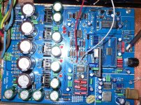
The receiver chip is indeed a CS8416, mounted on its own removable board. The DAC likewise, though the board is double sided, very small signal paths, so I doubt I'd be able to rattle up an equivalent. That leaves me with unsoldering the dac and soldering in a new one (assuming its the dac that's fried). There are the two OPA 2604au on the underside as well. Sounds like I'll likely fry the new DAC doing this (given my abilities).
Here's a snap of the board. I found zilch about it on the web (but only from a cursory search on Google).
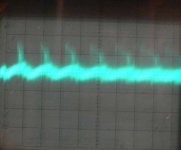
Attached is also a bad image of the I-out output signal. My scope is having a bad morning, and I couldn't hold the probe (discharged this time), camera, and adjust intensity/focus all at the same time. Apologies. The chip is seeing whatever load the manufacturer put on it. The settings are 1 microsec/div, and 10mV/div. The basic pattern seems to be the same on both channels and on the Vout as well.
Here's a snap of the board. I found zilch about it on the web (but only from a cursory search on Google).
Attached is also a bad image of the I-out output signal. My scope is having a bad morning, and I couldn't hold the probe (discharged this time), camera, and adjust intensity/focus all at the same time. Apologies. The chip is seeing whatever load the manufacturer put on it. The settings are 1 microsec/div, and 10mV/div. The basic pattern seems to be the same on both channels and on the Vout as well.
Attachments
Last edited:
I suspect you are on a loser with this tbh...
But never say never... if it helps, SMD is workable but practice on something else first.
http://www.diyaudio.com/forums/parts/127924-working-smd-how-do-without-specialised-tools.html
But never say never... if it helps, SMD is workable but practice on something else first.
http://www.diyaudio.com/forums/parts/127924-working-smd-how-do-without-specialised-tools.html
I'm still very much doubtful that you fried the dac chip, but I just saw that same plug-in PCM1798 module on ebay yesterday. Here it is for only $35:
PCM1798 module for Upsampling 24/192 DAC mainboard, USB | eBay
So, you can avoid the SMD soldering, which takes a lot of practice to do without damage to chip or board traces, for not a whole lot more than the two or three dac chips you'd likely end up needing for successful soldering in.
PCM1798 module for Upsampling 24/192 DAC mainboard, USB | eBay
So, you can avoid the SMD soldering, which takes a lot of practice to do without damage to chip or board traces, for not a whole lot more than the two or three dac chips you'd likely end up needing for successful soldering in.
I will definitely take your suggestions on board re SMD practice. I am not the tidiest solderer around. One more question, is it worth it? I have enjoyed this DAC but for not a lot more outlay should I replace the mobo and keep the beefy PSUs etc? If that is prudent any suggestions?
Many thanks to you both Mooly and Stephensank for helping this enthusiastic rather than advanced DIY'er. Much appreciated!
Many thanks to you both Mooly and Stephensank for helping this enthusiastic rather than advanced DIY'er. Much appreciated!
It's only worth it if it fixes it for a reasonable outlay. I think we have to be realistic and assume the worse. Remember it's not a "normal" failure mode... it's been zapped.
And you would have to practice on old PCB's first... modern remotes often have SMD chips in them... and be prepared that it may well not be a runner in the end.
Perhaps if you can get a replacement at reasonable outlay then that's the best option.
And you would have to practice on old PCB's first... modern remotes often have SMD chips in them... and be prepared that it may well not be a runner in the end.
Perhaps if you can get a replacement at reasonable outlay then that's the best option.
- Status
- This old topic is closed. If you want to reopen this topic, contact a moderator using the "Report Post" button.
- Home
- Source & Line
- Digital Source
- Hi, I just fried my DAC. Suggestions?