Hello guys I'm Guido from Italy .
I'm happy to discover this forum.
I have a question about an upgrade of my headphone amp Pro-Ject Head Box II to improve frequency response, sound, ecc...
The biggest trouble is substitution of op-amp that is an JRC2068 : what is the best choice op-amp for substitution ?
NE5532 or NE5534 , OPA1641 , OPA 2134 , LME 49723 , or other ?
For the Manufacter ? Texas Instr, National , Burr Brown , Analog Devices or
others ? Is it advisable cooling these op-amp ?
Do you think the new op-amp upgrade increase the temperature of other components , example in alim section in voltage regulator ?
For other components like capacitors I see Elna or Panasonic FM Caps and maybe I make an upgrade also of ext alim 16 V with other with more power ?
Can you give me some suggests ?
Thanks
Guido
The JRC2068 (same as the NJM2068) is one of the op amps used in the O2 headphone amp. You may want to read through the op amp comparison the designer of that amp did here
NwAvGuy: Op Amp Measurements
between the NJM2068 and others.
NwAvGuy: Op Amp Measurements
between the NJM2068 and others.
1. Forget about simple parts swapping for now. That rarely results in any tangible improvements when you've got a relatively modern concept with decent parts quality and construction (which applies to this amp).
2. Trace out the schematic, or at least determine the values of several components. Expect something similar to an Eaton amp, modified for single supply operation. If it's got an external 16 V supply, the regulator in there probably is an 7812?
Parts of interest would include:
* Output series resistors. The Head-Box II is reputed to be on the higher side in terms of output impedance, so that's definitely something that could be improved depending on what the resistor values turn out to be (I'd guess something in the 22..100 ohm range). The effect would vary depending on headphones. Even picky fullsize cans tend to be happy once they see less than 10 ohms, so I'd install 4.7 or 5.6 ohm jobs. But let's see what's in there now.
* The buffer stage's emitter resistors, and number of diodes. That would allow determining approximate idle current. (Of course you can always measure the voltage drop across the emitter resistors once their value has been determined.)
* Gain-setting resistors, more out of curiosity.
The concept unfortunately requires output coupling capacitors, and if I recall the inside shots correctly, the unit comes with 220 µF ones stock. That's a perfectly decent value, though if you can make some 470µ bipolar(!) ones fit "somehow", those should be an improvement in measured perforrmance (low-frequency distortion) at least.
Thanks guys for your precious anwser and suggests.
To agdr for the link: many interesting article in that site,long to read but I shall read it all.
To sgrossklass for his suggests for modding.
About this I tell you some things :
- regulator is a 7815 !!then if I have read well datasheett of JRC2068 and NE5532 is enough to supply both op-amp
- Below You can read all modify that I read here :
Random Acts of Upgrades: The Upgraded Pro-Ject Head Box Mk II
-1000uF caps were upgraded from 16V to 25V. This is more of a longevity issue than sound.
-Input caps C13, 14, 16 and 17 were upgraded from 4.7uF to 22uF. For two reasons. First, they are almost the smallest FM caps I could find. Second, I wanted to beef up the bass response.
-Output caps C8 and C10 were upgraded from 470uF to 1,000uF. Again, to improve the bass response at the headphones.
-Op-Amp replaced with an NE5532. I know I dissed it as old, but it was a good old op-amp and I have them lying around.
So you know because I have think that these modify op-amp and other are not expensive and possible first the op-amp NE5532 instead of JRC2068
Don't you think this is right ?
BYE
Guido
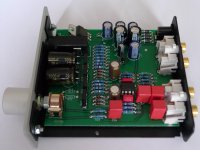
That´s what I did with my Head Box II:
1) Replaced the output caps with 1000 µF Panasonic FC
2) Replaced the (electrolytic) input caps with film caps
3) Installed a socket for the opamp (now LM4562)
4) Replaced the filter and bypass caps for the opamp
Remarks:
1) This is the only modification that is really needed,
especially if you use low impedance headphones.
2) The input caps after the volume pot (and the output
caps are needed to block DC (because of the single
supply). The input caps before the volume pot could
be ommited (shorted) if you are sure none of your
sources has DC on the output. (Such DC will ruin the
the volume pot.)
3) Use a dual opamp which is unity gain stable (NE5532,
LM4562, LM49720 ...) or leave the JRC2068 in place.
Personally I had never the "night and day difference"
some people report when trying different opamps.
(I have yet to hear an opamp that beats competent made
discrete class a circuity.)
4) Most likely not needed, but I had the parts at hand and
while I´m at...
The volume pot is crap and could be replaced by something
better, but I´m not sure if it is worth it. (Mounting Pirelli
racing tires on a cheap car does not make a Ferrari out of it).
Attachments
Wow gk7 ,are oyu author of the ariticle in those blog ?
If yes, it's fantastic this is what I'm look for.
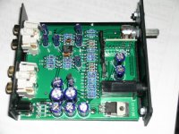
The board of my Pro-Ject Head Box MKII has little 2 differences :
1-vol pot no solded on board directly , but on an little adapter
2-I ahve only VD4 diode empy VD3 and VD2 and a VD1 haa his two terminal wired.
Can you have mofify also diode section ? Diodes seems to be 1N40404 , is it right ?
Is necessary also modify diode section ?
Can you tell me also Manufacter reccomended for rach componenent and where I can bur them on web ?
Se my attachment. to understand what I mean.
BYE
Guido
If yes, it's fantastic this is what I'm look for.
The board of my Pro-Ject Head Box MKII has little 2 differences :
1-vol pot no solded on board directly , but on an little adapter
2-I ahve only VD4 diode empy VD3 and VD2 and a VD1 haa his two terminal wired.
Can you have mofify also diode section ? Diodes seems to be 1N40404 , is it right ?
Is necessary also modify diode section ?
Can you tell me also Manufacter reccomended for rach componenent and where I can bur them on web ?
Se my attachment. to understand what I mean.
BYE
Guido
Attachments
Sorry but I need for explanations about your upgrade
1- what' the reason for substitution of the electrolytic input caps with film caps ? Electrolitic are polarized film no . What type and manufactures for film cpas ?
2- 4) Replaced the filter and bypass caps for the opamp. Sure you are more expert than me e nad maybe you have also electric shema of Head Box II but please can you tell me exactly what it the filter and caps for the opamp ? For by pass you mean unsolder this caps or other ?
Excuse me I am not an expert , be patience with me.
Thanks
Guido
No I´m not the author of that blog. The diodes
are 1N4001 or 1N4007 cant´t read it on the photo.
http://www.diodes.com/datasheets/ds28002.pdf
Any of them would do at 16V.
At your board Project has changed this from full
wave rectification to a single diode. I have no
idea why, they are only a few cents.
I would change this to four diodes, but maybe someone
else has an idea why this might have been changed.
The Wima MKS and Panasonic FC capacitors are available
at Mouser:
MKS2-.1/63/5 WIMA Polyester Film Capacitors
MKS2B044701K00KSSD WIMA Polyester Film Capacitors
EEU-FC1E102 Panasonic Electronic Components Aluminum Electrolytic Capacitors - Leaded
EEU-FC1E101S Panasonic Electronic Components Aluminum Electrolytic Capacitors - Leaded
Maybe they had issues with heat dissipation in the regulator (e.g. resulting solder fatigue)? Note how inconsistent its mounting seems to be. They originally intended it to be screwed to the board for good heat transfer and mechanical stability.
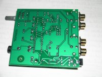
Do any of you guys have a picture of the bottom side of the PCB? Most of the signal routing seems to be going on there.
So far, R1 and R2 seem to be current limiting resistors between supply/ground and output driver collectors.
R15/17/18/20 (plus another set of same values on the other channel) include two 3R3 (emitter resistors?), one 10R (?) and one 15k (feedback?). 3R3s for emitter resistors would mean about 100 mA of quiescent current. Those power transistors should get nice and toasty @ 750 mW each. With the full-wave rectifier, the regulator would then have to dissipate about 800 mW, which explains the (planned) heatsinking setup.
Last edited:
@ gk7
Thanks for suggests but what mean exactly with " and bypass caps for the opamp " ?
@ sgrossklass
On attachment rear of my board .
Differences between mine and gk7 board can allow me to modify also diode section , then ?
Changing op-amp from JRC2068 to NE5532 or LM4562 or LM49720 ecc. we will have problem of power voltage and cooling of op-amp ?
See attacment.
BYE
Guido
Attachments
Bypass caps for the opamp:
These are the small ceramic caps nearby the opamp.
I changed these to Wima MKS 0.1 µF and the corresponding
electrolytics to some Elna electrolytic caps (the brown-gold
colored ones in my photo). This is probably not really needed,
but I don´t like ceramic caps and happend to have the parts at hand.
Quiescent current and temperature of the output transistors:
I haven´t measured their current, but yes they do get hot. I
leave it on all the time and had no problems for two years now though.
Soldering:
This is made with RoHS conforming unleaded solder and I had a hard
time when desoldering parts. That said I probably would only change
the output electrolytic caps to better quality and the largest value
that still fits and the input caps to better quality, if I had to do
it again.
The regulator does not get hot? Hmm. It should, at least when hanging in mid-air.
Could it be that Guido's unit uses an external DC power supply? Would explain the diode setup. If it delivers 16V=, the regulator would obviously not get hot (but not work properly either, it needs to drop ~2 V at least). 16V~ with a peak rectifier would give about the same result.
What I can already see from the board is that the Class-A output stage appears to be run open-loop - hence the relatively high current. As I suspected, the 3R3s are the emitter degeneration resistors, 10R is output series R, and the 15k appears to be for diode bias (OP-out -> 3x D --> 15k --> GND). The electrolytic between OP and buffer is connected in parallel to the bias diodes for reduced distortion.
Not sure about gain yet.
The regulator does not get hot? Hmm. It should, at least when hanging in mid-air.
Well "hot", not overly so.
Could it be that Guido's unit uses an external DC power supply? Would explain the diode setup. If it delivers 16V=, the regulator would obviously not get hot (but not work properly either, it needs to drop ~2 V at least). 16V~ with a peak rectifier would give about the same result.
No idea. Mine is AC.
What I can already see from the board is that the Class-A output stage appears to be run open-loop - hence the relatively high current. As I suspected, the 3R3s are the emitter degeneration resistors, 10R is output series R, and the 15k appears to be for diode bias (OP-out -> 3x D --> 15k --> GND). The electrolytic between OP and buffer is connected in parallel to the bias diodes for reduced distortion.
Do you have a schematic ? I don´t think it´s a open-loop buffer. And if this qualifies as class A ?
@ gk7
Thanks now I have understand . I have yet only a doubt if I modify diodes section is right for me consirìdering the differences of mt circuit board.
I confirm my external power supply is an 16 V AC.
Referring to aritcle in agdr link in previous page about op-amp comarision I think to change op-amp with a NE5532 first and listen , after try with others to compare acoustic results with my ears , not with a instrument.
About other op-amp instead of NE5532 other to try could be :LM4562, LM49720 and what other double op-amp and made by Ti, National or who ?
BYE
Guido
I think you're right, I finally saw traces going back to the feedback R/C from R8/R20. My eyes need a break now...I don´t think it´s a open-loop buffer. And if this qualifies as class A ?

It's a high-bias complementary AB buffer at the very least. Normally it'll stay firmly within class A operation, only a load below about 60 ohms could make it transition to AB if it gets loud. Still, about 70 mArms in class A should have most normal headphones covered pretty well.
Dear guys you are sometimes too technical for me and I can't follow you, but I'm happy to talk with because I have much possibilities to understand many new things.
Few hours ago I've changed original op-amp JRC 2068D with an NE5532 of Ti that is the only one component that I have found in resellers near my home , other I will buy on web to Moser or other.
Sound seems better for 2 reasons :
1- little more bass, that are deeper and with little more level
2- More speed response on transient expecially on bass and mid-bass frequency
Only listen some recording from CD or mp3, flac, ecc I listen likev a background noise at higher level , but this happen also on phone out of my sound card .
I use for input for Pro-Ject Head Box II Line Level Out of Sound Card that is a
Cakewalk UA-25EX .
Do you think about this ? With a better DAC should I have a bettere sound quality ?
( I'm tempted to modify also Sound card , Do I go insane ? )
By that you have wriet over , do you suggest me that bettere non modify diodes section?
Any cons for other op-amo to try and for best manufacter ?
Thanks you again.
BYE
Guido
There are certain limits to what you can do without the necessary know-how and means to verify performance. You pretty much have to rely on tutorials from people who are sufficiently capable. Blind component swapping tends to be pointless.
I have not yet managed to identify all the gain setting resistors yet. One is in parallel to the little ceramic cap, should be either a 6k8 or 68k. I assume impedance at both opamp input terminals is mid-high.
You can try some of the usual suspects like OPA2132 and maybe LM4562. Not extremely much current noise if possible, good CMRR preferred. With a socket in place, stay far away from anything remotely prone to oscillation (e.g. the notorious OPA2604).
Performance should be just fine with any (decent) opamp that does not misbehave. A little more or less noise here and there, but other than that any audible differences should be very small to inexistant (placebo effect is strong, don't forget). The buffer already takes care of output loading, which tends to be a major bottleneck otherwise.
If you really want to hear a difference, try run-of-the-mill opamps like TL072, LM358, LF353 or MC1458. These are cheap, with the LM358 and MC1458 probably being the crappiest of the bunch.
Last edited:
@ sgrossklass
Notices always interesting .I'm according to you I don't have the necessary know-how to to start form zero and modify any electronic circuit.and for this reason I want to use solution form article at link I have write in first post as also gk7 has talked about with his personal and valid notes.
So I think to make a good work with no hazard in this way.
I'm thinking about amplifier out impedance and out level necessary to drive good headphone from low to high impedance.
Considering that high impedance headphone over 300 ohms are pro and are very expensive for me, the range of impedance and then price for me also in the future will be max 250 $with Project head box II drive this headphone good.
Now I have an AKG K240 MKII with 32 ohms and amplifier cons > 30 ohms then I am on limits.
Infact setting volume of PC out in software player or windos or Ubuntu at 0dB level and volume of sound card near max level quite often the volume of headphone is not high also with out level of amplifier on max .
Is it possible to change out impedance of amplfier downwards to have a higher level of output without too difficult modifications of circuit , for example changing resistor, with lower ,in series to out of headphone.
Maybe I'm going insane, but please don't put your wire in my brain and willyou still let me join in the game , as Pink Floyd sing.
BYE
Guido
- Status
- This old topic is closed. If you want to reopen this topic, contact a moderator using the "Report Post" button.
- Home
- Amplifiers
- Headphone Systems
- Upgrade Pro-Ject Head Box II headphone amp