Hi,
This is my first post so bear with me please,
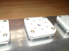
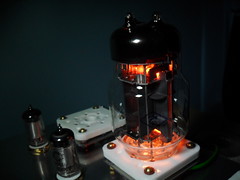
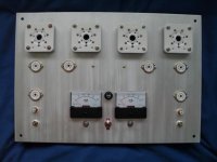
I have been collecting parts to build the Tim Mellows OTL for about 3 months now and have now started the build..
This is my second recent valve project , I did build a Mullard 5-10 back in the 70s so I chose the Mullard 3 -3 stereo as my return valve listening (mainly due to having the ef86 /el84 tubes + transformers from an old tape recorder) it sounds fantastic but it is not quite loud enough.
I have spent the year playing with different circuits and Tim,s circuit seems the most sensible OTL yet, so I have decided to go with it... I will post pictures of the progress as I go.
This is my first post so bear with me please,
I have been collecting parts to build the Tim Mellows OTL for about 3 months now and have now started the build..
This is my second recent valve project , I did build a Mullard 5-10 back in the 70s so I chose the Mullard 3 -3 stereo as my return valve listening (mainly due to having the ef86 /el84 tubes + transformers from an old tape recorder) it sounds fantastic but it is not quite loud enough.
I have spent the year playing with different circuits and Tim,s circuit seems the most sensible OTL yet, so I have decided to go with it... I will post pictures of the progress as I go.
Last edited:
Hi smith01793 only one of the images is coming up for me. If I open the links in a new tab they work. You might want to try attaching the images direct.
Click the Go Advanced button and you have a section to manage attachments.
edit: make that two are visible the last one works too.
Tony.
Click the Go Advanced button and you have a section to manage attachments.
edit: make that two are visible the last one works too.
Tony.
Last edited:
Hi wintermute,
thanks for the info, I will post more pictures and with more info as I go
you can view my all mypictures on flickr tony_smith_p75@yahoo.com
thanks for the info, I will post more pictures and with more info as I go
you can view my all mypictures on flickr tony_smith_p75@yahoo.com
To me, and no offence to Tim or anyone else--The design is fundimentally flawed in its feedback loop.
The FB gain changes depending on input vol-pot position, this is sure to change the character of the sound depending on the volume control position!
Ive tried this type of FB, and was never happy with this 'colouring' effect.....
The FB gain changes depending on input vol-pot position, this is sure to change the character of the sound depending on the volume control position!
Ive tried this type of FB, and was never happy with this 'colouring' effect.....
To me, and no offence to Tim or anyone else--The design is fundimentally flawed in its feedback loop.
The FB gain changes depending on input vol-pot position, this is sure to change the character of the sound depending on the volume control position!
Ive tried this type of FB, and was never happy with this 'colouring' effect.....
I tried measuring the input impedance at the grid of the input tube V1a, and it seems to be about 1.5K. This is very small compared with R1, which is 34K. I think this means that the effect you are speaking of, although real, is rather small. If my estimate is correct, I think it means the feedback, which is nominally 26dB, changes by less than about 0.5dB as the volume pot is varied. Certainly, in practice, I find no discernible change in the feedback as a function of the volume pot setting.
As Tim Mellow remarks in his article, an alternative is to hook the input to the grid of V1b instead.
Chris
Last edited:
I don't prefer this type of NFB too , but if you put a 100Kohm resistor and connect the volume in the input of the preamp then it will have no problem . And something else , if a small amount of DC voltage occurred in the output it will lead to a change in the bias point of the input tube ..To me, and no offence to Tim or anyone else--The design is fundimentally flawed in its feedback loop.
The FB gain changes depending on input vol-pot position, this is sure to change the character of the sound depending on the volume control position!
Ive tried this type of FB, and was never happy with this 'colouring' effect.....
Interesting comments RE the Tim Mellows design..
I chose it for two main reasons,
1) the total cost of the build will be about the same as the tubes and transformers for something like a 300b build.
2) In my experience... the more simple a design, the better results.
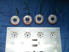
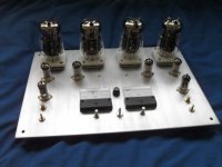
I am still working on perfecting the anodising.. once the top plate is anodised the build can start hopefully this should not take me too long as I have booked a week of work
I chose it for two main reasons,
1) the total cost of the build will be about the same as the tubes and transformers for something like a 300b build.
2) In my experience... the more simple a design, the better results.
I am still working on perfecting the anodising.. once the top plate is anodised the build can start hopefully this should not take me too long as I have booked a week of work
"Double up on the output tubes that givs you more power. "
It can't be as easy as JUST doubling up on the OP tubes. You would need to increase the filament transformer capacity and the split supply power transformer capacity if you want to do this. And can the driver stage deal with two more O.P. tubes? Perhaps the best choice for me is to make two monoblocks using the existing transformers specified. Now that might increase the power out to about 50 watts @ 8 ohms IF the driver stage is capable of handling the two extra tubes. WOuld anyone care to comment on this?
Thanks,
Mark
Of course its not so easy to double the output power , and the anodes of the two EF86 can't drive 4 6C33C , with large input capacitances plus the Miller capacitances , in this case you want cathode follower to drive the output tubes ."Double up on the output tubes that givs you more power. "
It can't be as easy as JUST doubling up on the OP tubes. You would need to increase the filament transformer capacity and the split supply power transformer capacity if you want to do this. And can the driver stage deal with two more O.P. tubes? Perhaps the best choice for me is to make two monoblocks using the existing transformers specified. Now that might increase the power out to about 50 watts @ 8 ohms IF the driver stage is capable of handling the two extra tubes. WOuld anyone care to comment on this?
Thanks,
Mark
- Home
- Amplifiers
- Tubes / Valves
- New Tim Mellows OTL project