Hello
Thought i'd share this with you......
I'm planning to build this Mike Tube Preamp....
Don Hicks Slow Blow 5687 tube microphone preamp vs planet _____________________________________slowblow slowblown
and am in the process of doing the layout for the turret board in Visio....so far so good. I dont intend on skimping for the preamp, apart from the audio input transformer for which i'm going to use a Sowter which is slightly cheaper.
So when it came to the power supply my budget is a bit on the thin side, so i did some research and this is what i came up with.....
Atx power supply...12v @ about 30A....enough to run an inverter circuit i found here.... 500w Modified Sine Wave Inverter Schematic Circuit Diagram which will give me 230V from the trany to be rectified and this circuit here... New Page 1 which will give me 45.6V for Phantom(also running off the ATX 12V), and of c ourse 12V from the ATX supply for the heaters.
Any thoughts or suggestions on this would be greatly appreciated.
Thank you.
Hi,
It may work as long as You can keep all the switching noise generated at the power supplies that You plan to use out of your preamp.
But to be honest, I prefer a simpler design, like the one on the original schematic, despite the fact that is is less power efficient than switching power supplies. The only real cost there is the mains transformer, but it will be easier to make your design simpler and quieter.
The inverter still requires the use of a transformer. Why not just buy a transformer that gives you the voltage you need? The overall cost should be about the same.
These guys have pretty decent toroids at good prices:
https://www.antekinc.com/
Then follow that up with the usual diode bridge and cap. Add a Maida regulator or one of my high voltage regulators if you get too much hum.
Alternatively, for a preamp, I'd consider looking at the many switching supplies made for nixie tubes that are out there.
I wouldn't skimp on the input transformer. If you want transformer coupled inputs, get a good transformer. Like Jensen, Cinemag or the like. Save your lunch money for a few more weeks and build it right. That's my opinion...")
~Tom
These guys have pretty decent toroids at good prices:
https://www.antekinc.com/
Then follow that up with the usual diode bridge and cap. Add a Maida regulator or one of my high voltage regulators if you get too much hum.
Alternatively, for a preamp, I'd consider looking at the many switching supplies made for nixie tubes that are out there.
I wouldn't skimp on the input transformer. If you want transformer coupled inputs, get a good transformer. Like Jensen, Cinemag or the like. Save your lunch money for a few more weeks and build it right. That's my opinion...
~Tom
If you want to fiddle with SMPS PSU why don´t you use the ATX unit ?
Rewind the transformer in it and use a voltagedoubler.
You have to locate the circuit containing the regulation and keep that intact the rest is adaptable to whatever voltage you need.
But as said earlier switching noise is a PITA.
Rewind the transformer in it and use a voltagedoubler.
You have to locate the circuit containing the regulation and keep that intact the rest is adaptable to whatever voltage you need.
But as said earlier switching noise is a PITA.
Thanks for your input,much appreciated.
I'm in the uk so am going to go for this....
Amp Maker: Guitar amp kits and parts :: Power transformers :: 240V/6.3V toroid power transformer
It's the cheapest i can find and looks like it will do the job. I'll also get a small cheap trany for the Phantom.
Again...many thanks
I'm in the uk so am going to go for this....
Amp Maker: Guitar amp kits and parts :: Power transformers :: 240V/6.3V toroid power transformer
It's the cheapest i can find and looks like it will do the job. I'll also get a small cheap trany for the Phantom.
Again...many thanks
Sorry to be a "party pooper", but the 1 A./6.3 V. filament winding of the linked toroid is not up to energizing the heaters of both a 5687 and a 12AU7, even if AC heating is to be employed. The linked PSU schematic shows a 12 VDC supply that feeds both the tube heaters and a B+ switching relay. The 12 V/3 A. winding shown is the minimum needed for the job. When a winding is rectified and cap. I/P filtered (as is the case here), approx. 1/2 the AC RMS current capability is available as DC. The tubes draw 600 mA. @ 12 V., leaving 900 mA. for the relay.
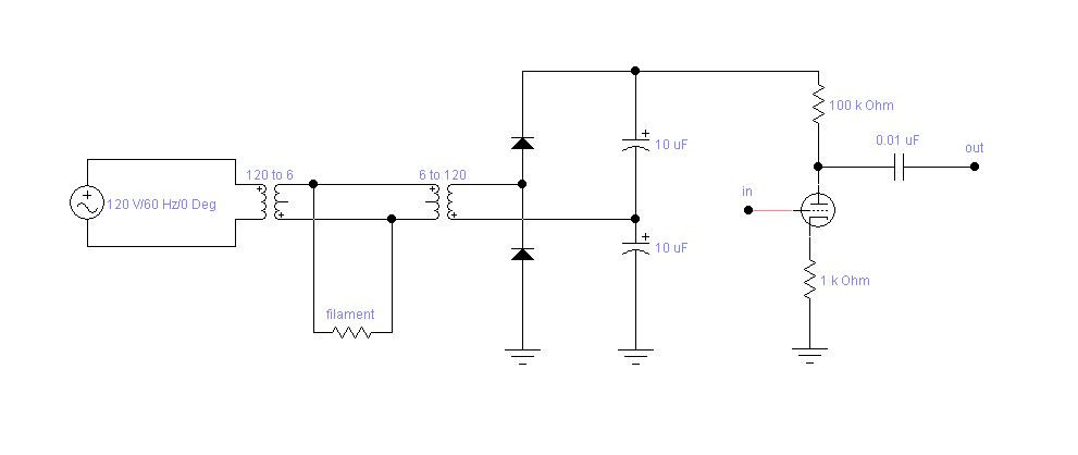
Flash circuit from a camera? -or- Two small transformers to step down then back up with a multiplier afterwords? 120vac to 6vac then 6vac to 120vac 2x multiplier to 240vdc? (or 120 to 12 then 12 to 120 x2 240)
Like this...
Like this...
Attachments
Last edited:
- Status
- This old topic is closed. If you want to reopen this topic, contact a moderator using the "Report Post" button.
- Home
- Amplifiers
- Tubes / Valves
- Poor man's power supply