There have been a few versions of the JLH Class A design around with MOSFET output devices, e.g. :
http://www.diyaudio.com/forums/solid-state/3075-jlh-10-watt-class-amplifier-44.html#post2836764
or a full MOSFET version :
http://www.diyaudio.com/forums/solid-state/2274-jlh-class-mosfets.html
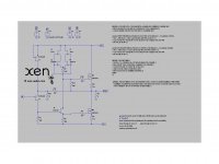
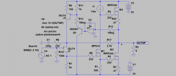
I took on the mental challenge on the train this morning to come up with a JFET / MOSFET version of the 2003 circuit at Geoff's excellent website :
The Class-A Amplifier Site - JLH Class-A Update
This is just quick and dirty draft version which is by no means optimised.
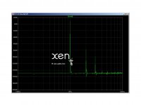
But the performance is more than decent, with some -90dB 2nd at 1kHz 1W 8R output.
Bandwidth is beyond 10MHz, if you believe everything in Spice.
")
Will give it some more thoughts when I have time. Perhaps a PCB later.
Patrick
http://www.diyaudio.com/forums/solid-state/3075-jlh-10-watt-class-amplifier-44.html#post2836764
or a full MOSFET version :
http://www.diyaudio.com/forums/solid-state/2274-jlh-class-mosfets.html
I took on the mental challenge on the train this morning to come up with a JFET / MOSFET version of the 2003 circuit at Geoff's excellent website :
The Class-A Amplifier Site - JLH Class-A Update
This is just quick and dirty draft version which is by no means optimised.
But the performance is more than decent, with some -90dB 2nd at 1kHz 1W 8R output.
Bandwidth is beyond 10MHz, if you believe everything in Spice.
Will give it some more thoughts when I have time. Perhaps a PCB later.
Patrick
Attachments
Very interesting circuit. Thanks for sharing.
It is interesting that you can get away with a small FET (K170) for the phase splitter. Usually, I don't like an all-FET design because of the use of high capacitance FET. For example, Tschrama uses IRF9510 for the input and IRF510 for the phase splitter in his Mosfet JLH.
This is the first time I see a J111 FET. Why not other common PJFET such as J74? Is it critical to use a certain type of FET here?
The output Toshiba FET (K3497) is also rare/new. I have no experience with this kind of FET, but I think the bass performance will be good. But JLH topology is already good with bass, so it will not be too important.
I noticed that you also modeled a Lateral FET (K1058). I'm not sure that Latfet will be superior. It is more linear compared to VFET, but in class-A that is not an important parameter. Trans-conductance could be more important? I will use K1341. Have you modeled similar FET such as IRF240?
Nelson Pass once mentioned (regarding BJT Aleph) that he never made a BJT-FET design that was "special". So it is either All-FET or All-BJT. That's why I like your new amp.
ADD: Ups, I don't like the R13. It seems too small. Alex Nikitin uses 1K but in a class-B design. I know that many had tried similar Mosfet JLH idea and it seems that the resistor is a must. Hmmm...
Last edited:
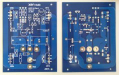
In another thread (http://www.diyaudio.com/forums/pass-labs/198012-jlh-plh-pc-boards.html) I presented my own JLH/PLH variant. I have made the PCBs and started testing just a week ago.
Last edited:
The circuit was a 1:1 translation of that at Geoff's website.
There are probably infinite other possible variants.
I posted this to create interest and discussions.
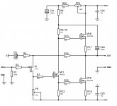
As to choice of FETs :
1) The input FET has to be P device if we want to use NMOS at the output stage.
2) 2SJ74 has to be GR grade to maintain sufficient open loop gain. This has to run at Idss in order to allow direct DC couple, and the Vgs of the MOSFETs are relatively low. On top of that, the GR grade is still obtainable, unlike the BL or V grades.
3) Any of the current sources can be 2SK170 cascode by J111. The J111 has a high Idss which when running at 8mA or so will give a decent 5V Vds for the 2SK170 that it cascodes. For simulation, I was lazy to trim Id, so I just use the same J74GR for CCS and for input device to make sure no offset.
4) The 2SK3497 can be found in many Accuphase power amps. It has high Yfs and yet low capacitance, ideal for here. The frequency response actually has a small hump with 8R load at ~10MHz. It can be tamed with a 2R 100n Zobel and the response is flat for all loads from 2R to 20R with bandwidth > 5MHz. You can also use the 2SK3163, which will not need any Zobel. The bandwidth is a bit less but still way over 1MHz. Having lower Yfs and C as in laterals might not be too good for stability.
As said, plenty of variants to improve this further. Please feel free to have a go and let us know.
Patrick
There are probably infinite other possible variants.
I posted this to create interest and discussions.
As to choice of FETs :
1) The input FET has to be P device if we want to use NMOS at the output stage.
2) 2SJ74 has to be GR grade to maintain sufficient open loop gain. This has to run at Idss in order to allow direct DC couple, and the Vgs of the MOSFETs are relatively low. On top of that, the GR grade is still obtainable, unlike the BL or V grades.
3) Any of the current sources can be 2SK170 cascode by J111. The J111 has a high Idss which when running at 8mA or so will give a decent 5V Vds for the 2SK170 that it cascodes. For simulation, I was lazy to trim Id, so I just use the same J74GR for CCS and for input device to make sure no offset.
4) The 2SK3497 can be found in many Accuphase power amps. It has high Yfs and yet low capacitance, ideal for here. The frequency response actually has a small hump with 8R load at ~10MHz. It can be tamed with a 2R 100n Zobel and the response is flat for all loads from 2R to 20R with bandwidth > 5MHz. You can also use the 2SK3163, which will not need any Zobel. The bandwidth is a bit less but still way over 1MHz. Having lower Yfs and C as in laterals might not be too good for stability.
As said, plenty of variants to improve this further. Please feel free to have a go and let us know.
Patrick
> But to be honest, R13 is enough for me not to build the amp.
> Do you think it is entirely possible to remove the resistor?
If I am not wrong then you might not fully understand how the JFET phase splitter works.
Contrary to the BJT version, the phase splitter driving the MOSFETs is one which works with voltage.
So you have to have R13, and nominally it should be the same value as R6.
I assume of course that you want to drive M1 & M3 with signals of the same voltage amplitude but anti-phase.
This is also why the cascode with J111 improves performance significantly.
Patrick
> But to be honest, R13 is enough for me not to build the amp.
> Do you think it is entirely possible to remove the resistor?
If I am not wrong then you might not fully understand how the JFET phase splitter works. Contrary to the BJT version, the phase splitter driving the MOSFETs is one which works with voltage. So you have to have R13, and nominally it should be the same value as R6.
Of course I don't understand how it works. Otherwise, I would have built my own amplifier, wouldn't I? But what I meant with removing the resistor was not just to remove it from your circuit, but to redesign without the resistor. May be there will be a challenge, but that is the price for a good sounding amp imo.
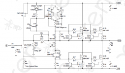
I prefer the topology used by knutn posted above. Phase splitter will be replaced with IRFD1Z3 (0.4A device). Input bias circuit is also welcome, especially with better regulated supply (or battery).
The "performance" of R13 is not something you can see from any simulator.
... The "performance" of R13 is not something you can see from any simulator.
I would add, there are many factors (not only a resistor at specific place) that can negatively affect final result - the sound. At the same time, these factors are hardly revealed not only by simulations, they are usually not measurable by standard equipment (except for maybe special dedicated equipment).
My practice nowdays is to judge about schematics only after prototyping and listening, in comparison with best reference components available to me. Such approach makes the process very slow, but the conclusions obtained are very reliable.
My practice nowdays is to judge about schematics only after prototyping and listening, in comparison with best reference components available to me. Such approach makes the process very slow, but the conclusions obtained are very reliable.
Maybe you know the secret pf circuit design better than I do .....
Of course I can build all the published schematics in this site, but I don't want to. You know that we don't have time for that mission
If you have to build amps, I believe you will do something to simplify the process of choosing the candidates. Simple process is to choose proven circuits that have been favored by many, or better, experienced builders.
If somebody build the new amp and swear that it is better sounding than the Fetzilla for example, of course I will build it, no doubt about it. But I have to say that my process of choosing the candidate has been proven to be accurate and useful
Hey Patrick,
Posted this in another thread but maybe this is a better place.
Posted this in another thread but maybe this is a better place.
Have looked into this before and going without output cap feels a little risky.
But if one added a simple servo from the output to steer the single FET CCS of the input FET we might be safe. Have done a few simple sims and it should work.
Have you consider siomething a little more hefty as driver? I have tried with IRF510 and 610 models and they seem to work well.
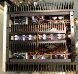
After a delay of a year and a half, the prototype is finally finished.
Works first time with no bugs. Sounds gorgeous.
Outstanding bass control and very smooth highs for such a hig bandwidth design.
The real circuit is of course more sophisticated than that in Post #1.
We'll publish eventually after another round of refinements.
Patrick
Works first time with no bugs. Sounds gorgeous.
Outstanding bass control and very smooth highs for such a hig bandwidth design.
The real circuit is of course more sophisticated than that in Post #1.
We'll publish eventually after another round of refinements.
Patrick
Attachments
- Status
- This old topic is closed. If you want to reopen this topic, contact a moderator using the "Report Post" button.
- Home
- Amplifiers
- Solid State
- All FET JLH Class A