Merry Christmas all!
I've been working on a new push-pull driver PCB. I mentioned it in the "Engineer's Amplifier" thread, but figured I should start a new thread for discussion, since it is a different project.
I wanted to come up with a driver that has some of the same characteristics as the Engineer's amp, but was a bit more flexible. Lots of requests for a similar amp that can use normal output tubes, for example. I also wanted something that has an extra gain stage, so NFB could be applied... partly for my own education, since I have not worked much with global NFB.
Like the engineer's amp, what I've come up with uses pentode drivers (either E80L or 6EJ7 or tubes with similar bases, or 12BY7 / 12HG7 / 12GN7) arranged as a diff amp with a CCS in the tail. A single triode (6J4/8532) gain stage sits in front, so you can apply gNFB to the cathode.
There are many more details on my web page: Push-pull driver board
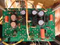
Right now, I have a proto board built, running a pair of triode-connected KT88's. So far it looks pretty good.
At this point, before I build any more boards, I'd love to get some feedback. Anything I should change or add? Within reason, of course")
One thing I already thought of was to add some jumpers so you could triode-connect the driver tubes.
If you have suggestions, please post them here, or shoot me an email.
Thanks!
Pete
I've been working on a new push-pull driver PCB. I mentioned it in the "Engineer's Amplifier" thread, but figured I should start a new thread for discussion, since it is a different project.
I wanted to come up with a driver that has some of the same characteristics as the Engineer's amp, but was a bit more flexible. Lots of requests for a similar amp that can use normal output tubes, for example. I also wanted something that has an extra gain stage, so NFB could be applied... partly for my own education, since I have not worked much with global NFB.
Like the engineer's amp, what I've come up with uses pentode drivers (either E80L or 6EJ7 or tubes with similar bases, or 12BY7 / 12HG7 / 12GN7) arranged as a diff amp with a CCS in the tail. A single triode (6J4/8532) gain stage sits in front, so you can apply gNFB to the cathode.
There are many more details on my web page: Push-pull driver board
Right now, I have a proto board built, running a pair of triode-connected KT88's. So far it looks pretty good.
At this point, before I build any more boards, I'd love to get some feedback. Anything I should change or add? Within reason, of course
One thing I already thought of was to add some jumpers so you could triode-connect the driver tubes.
If you have suggestions, please post them here, or shoot me an email.
Thanks!
Pete
Attachments
I have a few different driver boards in various stages of completion. One that is currently breadboarded uses a pair of 9 pin pentodes in LTP for the driver stage and a dual triode in LTP for the input stage. I have stuffed several different tubes into it and also tried a few things that I'm sure you haven't...yet.
My observations:
Some 6EJ7's can be good TV jammers (VHF oscillations). Grounding pin 6 helps calm them down. Pin 6 can't be grounded on all tubes, so a short jumper is good.
6EH7's are considered useless for audio but work OK for LTP if you don't need a lot of drive voltage.
I have experimented with the screen bypass cap (and zener where used), and found that for most tubes connecting it to the cathodes generally works better than ground. If you think about it connecting it to ground applies some negative feedback to the screen in a manner similar to UL operation. The VR tube acts like a bypass cap, but you might want to add a .01 or so across it for noise control. Too big a cap may make them unstable.
If you really want to try something crazy, take the local feedback from the output tube plates to the driver screens. Since the screens invert the phase, you need to "crossover" the feedback resistors (take the feedback from the other output tube's plate). I first learned this on my red board and it can compensate for output tubes with mismatched Gm. It doesn't work with all tubes, and you need a resistor to ground to keep the screen voltage down with big plate voltage on the output tubes.
I tend to run things like mosfets and CCS's off of the negative voltage bias supply. A simple half wave rectifier doesn't work very well if you need 50 ma or more. Some builders will be in 50 Hz countries making matters worse. In the case of the typical Hammond transformer with the single tap, it's all that's available, so it's your call. If you have room on the next itteration 4 diodes and a jumper will allow both.
Mismatched output tubes are more common than matched ones. A seperate bias adjustment for each tube, or an offset adjustment like the red board is a worthwhile addition.
Suggestions: I would want
1. provision for CCS in the first tube's plate circuit (or not)
2. provision for 2 series components in the first tube's cathode so that one can use a LED and a resistor for NFB (or not)
3. If there is enough room, I would have dual patterns for the tubes so one can use noval or octal tubes (my preference).
Some good ideas. Here is what I've implemented:
1. Jumpers to triode-connect (or pentode-connect) the driver tubes
2. (Optional) cap across the VR tube (0.01uF)
3. Changed bias rectifier to FW bridge (you can always jumper a diode for half-wave)
4. Added an output balance pot
5. Added an (optional) CCS in the plate of the input tube (replaces resistor)
6. Added an (optional) LED in series with the cathode bias resistor of the input tube
7. Added an (optional) RC from input tube plate to GND (additional FB compensation)
8. Added jumpers to connect pin 6 of the driver tubes directly to the GND plane
Sorry, an octal alternate would be very difficult - it would make the board bigger (I want to keep it compact), and there are not a lot of good octal pentode drivers (IMHO).
An updated schematic is here: http://www.pmillett.com/file_downloads/ppdrv_sch_revB.pdf
Keep the ideas coming!
Pete
Plans to offer a PCB fot the power supply ?
There really isn't anything to the power supply, so no PCB planned. I'll use a tube rectifier and CLC filter. I did design a "cap board", just a little PCB with two snapmount electrolytics, just because I'm tired of trying to find a good way to chassis mount them...
Pete
and there are not a lot of good octal pentode drivers (IMHO).
The drivers job is to take a small signal and amplify it to a level capable of cranking big power out of some insensitive tubes. You may need 300 volts of drive to run 845's in class A2 or AB2. To do this with a pentode requires a good bit of Gm. The usual 6SJ7 comes in around 1600 uMHOS. I had the best luck with a 6K6 (2300)or a 6V6 (4100).
There are several good 9 pin driver candidates with Gm as high as 25000.
Hi Pete,
do you think it would be possible to apply plate-to-plate (aka Schade) feedback with this driver board?
It might be interesting to use this in a Baby Huey-sytle setting i.e. with KT88 output tubes. I am not sure if your driver could be used instead of the diff amp in the Baby Huey.
(link to Gingertube's circuit here )
This "Huey" might not be much of a "Baby" any more...
Or is this beyond the scope/idea of the circuit (I don't want to go too far off-topic)?
Cheers,
Martin
Hi Pete,
do you think it would be possible to apply plate-to-plate (aka Schade) feedback with this driver board?
Yes, though I implemented it a little differently - I have positions for resistors from each driver plate to both B+ and to an off-board connection, which could be to the output plate, or to the unltralinear taps. So you can dial in the amount of feedback by adjusting the ratio of the two resistors.
You can also leave out the input tube and build this as a 2-stage amp. Maybe I will add some provisions to apply gNFB to the other side of the diff amp, as is done in the Baby Huey amp you reference...
Pete
This little PCB are already for sale ?
Nope, not yet... it will be a few weeks.
Pete
Yes, though I implemented it a little differently - I have positions for resistors from each driver plate to both B+ and to an off-board connection, which could be to the output plate, or to the unltralinear taps. So you can dial in the amount of feedback by adjusting the ratio of the two resistors.
You can also leave out the input tube and build this as a 2-stage amp. Maybe I will add some provisions to apply gNFB to the other side of the diff amp, as is done in the Baby Huey amp you reference...
Pete
That sounds really nice!!!
So, when you say universal, you really DO mean universal.
Sounds like a lot of thoughts went into this board.
I appreciate that.
Thanks!
Martin
OK, I made a few more tweaks, and wrote up a full circuit description on the web site. Please have a look, let me know of any errors you see, or any other requests...
Push-pull driver board
Thanks,
Pete
Push-pull driver board
Thanks,
Pete
"or any other requests..."
Would be nice to have some resistor positions, with cathode fdbk nodes, in the two cathodes of the 12GN7 drivers. (Like in the RCA tube handbook for their 50 Watt amplifier). But that likely won't work out with the current self splitting of the driver stage. Could maybe leave room for a small (optional) HV Mosfet Concertina splitter stage in front of the drivers to operate the two driver grids then.
Would be nice to have some resistor positions, with cathode fdbk nodes, in the two cathodes of the 12GN7 drivers. (Like in the RCA tube handbook for their 50 Watt amplifier). But that likely won't work out with the current self splitting of the driver stage. Could maybe leave room for a small (optional) HV Mosfet Concertina splitter stage in front of the drivers to operate the two driver grids then.
"or any other requests..."
Ah, a little too late... PCBs are on their way to me now...
I'm in Asia at the moment, but will post more info when I get home this weekend.
Pete
Watch out for the frog in hot chili oil, The frog is OK a little crunchy, its the chili oil that gets you the next day.... I had a stint in Langfang last yr, quite an experience, no time to chase audio parts.
I like the PCB, 6L6 or 6LB6 family should work great with it. Bias for the screens of the 6LB6's?? It could be done off board zener stack on power supply. Lots of feedback and bias options...I especially like the CCS on the second stage and Schade feedback from the output tubes. I appreciate that your work will open up the realm of tube amps to nubies eager to try their hand at it. I wish that this was available a couple yrs ago when I decided to try the enlightened path of tube amps, it is a great step up to what was available then, looks like a great breadboard to learn from. A far nicer PCB than the toner transfers that I've been making..
I like the PCB, 6L6 or 6LB6 family should work great with it. Bias for the screens of the 6LB6's?? It could be done off board zener stack on power supply. Lots of feedback and bias options...I especially like the CCS on the second stage and Schade feedback from the output tubes. I appreciate that your work will open up the realm of tube amps to nubies eager to try their hand at it. I wish that this was available a couple yrs ago when I decided to try the enlightened path of tube amps, it is a great step up to what was available then, looks like a great breadboard to learn from. A far nicer PCB than the toner transfers that I've been making..
Last edited:
How's the progress on these PCB's?
I have the new rev boards (red, or course) in house now... I've been traveling again (just got back) so I have not found time to document it on the web site.
I will try and get at least some info and pictures on the website and get them on eBay this weekend... it might take a little longer for me to actually build up a pair for myself.
Pete
- Status
- This old topic is closed. If you want to reopen this topic, contact a moderator using the "Report Post" button.
- Home
- Amplifiers
- Tubes / Valves
- Mono push-pull driver PCB