anyone using an inrush current linter on their tube amps. this one is rated at 12 amps. so would it work on my amps that have 10 amp fuses?
4pc Inrush Current Limiting Limiter SG333 12A 5ohms 5 | eBay
4pc Inrush Current Limiting Limiter SG333 12A 5ohms 5 | eBay
Inrush current limiter
do you want to limit the inrush of B+ ?
if so the solution is a Capacitor Multiplier, this circuit will give slowly way to the B+, so you will see your B+ voltage rise slowly, in accordance with the value of the charge resistor and capacitor value
http://www.el34world.com/Forum/index.php?action=dlattach;topic=12801.0;attach=27213;image
http://www.el34world.com/Forum/index.php?action=dlattach;topic=12801.0;attach=27289;image
the added resistor (R2 470K) give the circuit the principal function of Capacitor Multiplier (with relatively little capacitor you'll have high ripple rejection)
without the 470K resistor the circuit helps to reject ripple, but acts more as a slow insertion circuit
as to change that time you can modify the value of the 33k resistor (charge resistor) the time insertion of the schematic with 33k resistor is around 4 seconds
agliostro
Hello,
I'm still relatively new to building tube amps but I can lend my experience with these. These were recommended to me by another on this forum and I put them in my Dynaco Mark VI's. The Mark VI is a brute of a power amp and in these amps they have been working just fine for almost two years. I replaced the timed delay relay tubes, which I still have, and haven't had any problems. I put them only on the B+ high voltage which gives you a delay on the B+ until after the bias voltage comes up.
The question I cannot answer is how durable they are. But in two years I haven't had a failure. I'm assuming, like a normal resistor they will fail to open? Where is the risk?
They can be found here: http://www.ge-mcs.com/download/temperature/920_325a.pdf
anyone using an inrush current linter on their tube amps. this one is rated at 12 amps. so would it work on my amps that have 10 amp fuses?
4pc Inrush Current Limiting Limiter SG333 12A 5ohms 5 | eBay
Have a look here:
http://www.diyaudio.com/forums/tubes-valves/190214-ntc-thermistor-soft-start-tubes.html
Regards
M. Gregg
Have a look here:
http://www.diyaudio.com/forums/tubes-valves/190214-ntc-thermistor-soft-start-tubes.html
Regards
M. Gregg
Hi all,
these thermistors do their job. But I rely more on a delayed Circuit braker in my fuse box. Most of my sockets are fused with 13A curve C circuit breakers. They allow higher inrush currents. Normally you will find B curve circuit breakers in domestic installations. C breakers does have twice inrush capacity than B breakers.
73
Wolfgang
A lot of missing details about your amps. Why a 10A fuse, to start with?
I agree,
What current are you drawing from the mains and what wattage are you dissipating in the amp? Remember that a fuse does not blow at the rated current some can be approx 1.5x the value.. I x V = W.
If you are having to use a 10A fuse because of inrush your fault current is going to be quite high. What rating is the mains cable to the amp? With resistive fault you may draw more than the cable can take and not blow the fuse...
 Reduce the inrush and fuse closer...
 Obviously if you switch off and back on you will blow the fuse because the thermistor will be hot and resistance will be low.
EG even if your drawing 500W from the mains with 110V ..4.6A ?
Just for fun measure your AC mains current... Also a Time lag fuse can be used..
Regards
M. Gregg
Hi
You have not given any data on the amp you want to limit currents on so it is difficult to be specific about your particular application.
However I have used thermisters to limit peak switch on currents in my tube and semiconductor amps for years. I install them in the primrary circuit of the transformer as recomended by national semiconductors and I have never had a problem.
I have bought mine from Rapid electronics and they are 10ohm 12 amp ones.
Don
anyone using an inrush current linter on their tube amps. this one is rated at 12 amps. so would it work on my amps that have 10 amp fuses?
4pc Inrush Current Limiting Limiter SG333 12A 5ohms 5 | eBay
When I first read about these inrush current limiters (I am a newbie), I thought they are neat devices and all I have to do is put one or two (with the "right" rating) before the main transformer and I am done. Apparently, not so simple. During my search for more information, I found the following site that provide good informations:
http://www.ge-mcs.com/download/appnotes/ntcnotes.pdf
Inrush Current Limiters - Power Thermistors - Home - Ametherm
Epcos's site also has a fairly straightforard application note on NTC.
I am sure there are many more sites on this topic. The ge-mcs site is very detailed and contains all the mathematical descriptions that you want to know but afraid to ask. The Ametherm site is very easy reading and gave a good overview. The Eillot Sound website has a good article on inrush current too.
Overall, based on what I read, a lot of people love the combination of resistor plus a relay by-pass. One can do the same with a thermistor, repalcing the resistor with thermistor. Other like to use some fairly elaborate softstart module. Interestingly, in Nelson Pass's F5 amp article, the PSU that was described contains only 2 CL-60 NTC and that PSU draw huge inrush current due to the big caps used.
Hope these helps
Lo_tse
A lot of missing details about your amps. Why a 10A fuse, to start with?
the amps come with 10 amp fuses. the amp uses 8 KT-90's and puts put 380 watts per mono block. I have 3 of them as well as 2 250 watt per mono block versions that have 8 amp fuses.
the amps each have two 3800uf capacitors of the primary rectifier.
the fuse size questions was to get input on if a 12A inrush limiter would work on a primary circut that draws 10 amps at max power. in reading the tech data on the various data sheets....there's an implication that the function has a lot to do with heat of the limiter...so when it says 50ohms cold and 5 ohms hot, not sure if that means it needs to get to 12 amps to get to 5 ohms.
Wall power into the room is thru a 220:120 step down wired as a balanced power transformer 60 - 0 - 60. The transformer is 50A's on the seconday side. two 30 amp breakers protect the transformer on the primary side....a 30 amp breaker for each 120v leg of the 220 circut. The actual wall jacks are a couple seperate 120 (60-0-60) volt outlets at 20amps using code required orange balanced power outlets .
Last edited:
A lot of missing details about your amps. Why a 10A fuse, to start with?
the amps come with 10 amp fuses. the amp uses 8 KT-90's and puts put 380 watts per mono block. I have 3 of them as well as 2 250 watt per mono block versions that have 8 amp fuses.
the amps each have two 3800uf capacitors of the primary rectifier.
the fuse size questions was to get input on if a 12A inrush limiter would work on a primary circut that draws 10 amps at max power. in reading the tech data on the various data sheets....there's an implication that the function has a lot to do with heat of the limiter...so when it says 50ohms cold and 5 ohms hot, not sure if that means it needs to get to 12 amps to get to 5 ohms.
Wall power into the room is thru a 220:120 50 amp on the secondary side step down wired as a balanced power transformer 60 - 0 - 60. The circut that feeds the transformer is 220 using two 120 volt legs each with a 60 amp breaker.
Without getting too curmudgeonly about it if you are not blowing the fuses or tripping the breakers the amplifier should be capable of withstanding the inrush current, it was designed to do so. Sounds like one of the larger VTL amps.. Use MDL type fuses rather than fast blow, and consult with the maker of your amp.
The 12A device you are talking about is probably 5 ohms cold and more like 0.1 - 0.2 ohms hot otherwise the voltage drop would be ridiculous and it would burn up in short order. Normally they need to dissipate a watt or two to be hot enough to operate on the low resistance end of their curve.
The 12A device you are talking about is probably 5 ohms cold and more like 0.1 - 0.2 ohms hot otherwise the voltage drop would be ridiculous and it would burn up in short order. Normally they need to dissipate a watt or two to be hot enough to operate on the low resistance end of their curve.
Useless for tube amps, check the spec of this device.
Better to use a series resistor bypassed after 1 second by a relay
Better bypassed by relay when it gets a voltage after rectifier and capacitor. I power relays from 12V filament DC source: if the voltage there is up that means all capacitors in separate rectifiers/filters are charged almost to the same level since they are all in parallel connected through the common series resistor in primary.
Better bypassed by relay when it gets a voltage after rectifier and capacitor. I power relays from 12V filament DC source: if the voltage there is up that means all capacitors in separate rectifiers/filters are charged almost to the same level since they are all in parallel connected through the common series resistor in primary.
That's what I use.....although the intermittent plug connection which creates a magnetic backlash will probably blow an overrated fuse before the relay has time to dropout and restart the cycle. The trick is a fast drop out relay to deal with this inconjunction with an active reset circuit.
richy
That's what I use.....although the intermittent plug connection which creates a magnetic backlash will probably blow an overrated fuse before the relay has time to dropout and restart the cycle. The trick is a fast drop out relay to deal with this inconjunction with an active reset circuit.
Trick: relay rated for lower voltage, with Zener in series.
Inrush current limiter
do you want to limit the inrush of B+ ?
if so the solution is a Capacitor Multiplier, this circuit will give slowly way to the B+, so you will see your B+ voltage rise slowly, in accordance with the value of the charge resistor and capacitor value
http://www.el34world.com/Forum/index.php?action=dlattach;topic=12801.0;attach=27213;image
http://www.el34world.com/Forum/index.php?action=dlattach;topic=12801.0;attach=27289;image
the added resistor (R2 470K) give the circuit the principal function of Capacitor Multiplier (with relatively little capacitor you'll have high ripple rejection)
without the 470K resistor the circuit helps to reject ripple, but acts more as a slow insertion circuit
as to change that time you can modify the value of the 33k resistor (charge resistor) the time insertion of the schematic with 33k resistor is around 4 seconds
agliostro
That's a fantastic idea for the DC side. Protects the rectifiers, capacitors and amplifier tubes.
I have been thinking of a delayed relay to short the inrush resistor on the AC side, without needing a LV supply. 230 Volt relays are reasonably cheap, so came up with this idea:
Any comments?

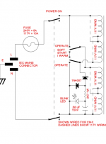
Alot of these circuits wouldn't work where I live; during the summer months there is intermittant and deep brownouts which would rely on a very fast dropout to avoid fuse rupturing. Relying on a DC level with a capacitor drag isn't my solution, for me it has to be a cycle per cycle interrupt and reset to void persistent fuse blowing or use a fantastically overrated antisurge fuse which wouldn't save the circuit.
richy
richy
- Status
- This old topic is closed. If you want to reopen this topic, contact a moderator using the "Report Post" button.
- Home
- Amplifiers
- Tubes / Valves
- power up inrush current limiter - anyone using?