Hi .
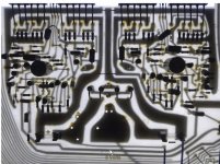
Im playing with this amplifier at the moment . A few things concern me related to the layout of the power traces. As you can see from the Picture the + - Rails starting at the fuses go first to the input section then there is a tap off the traces a little further along and then to the output stage last . From what i have learned so far this is not a good way to do things . Any thoughts on this would be welcome.
Kind Regards
Ian
Attachments
Typically you want to have the large currents, including those of any fairly large de-coupling caps about the output stage (don't see any in this circuit ) and their gnd return currents, separate from the IPS/VAS supply and gnd return currents. IPS/VAS voltage sources should have separate decoupling from the main supply rail.
) and their gnd return currents, separate from the IPS/VAS supply and gnd return currents. IPS/VAS voltage sources should have separate decoupling from the main supply rail.Thankyou CBS240.
Would you belive the PCB piccy i posted is from a production amplifier. I was thinking about the decoupling caps as nearly every other amplifier scematic i have looked at has decoupling caps about the out put stage. Most seem to use around the 100uF mark so i will add some . I also did not like how the power rails where shared between the two channels so have done some cutting and altering of the pcb tracks and added some decent thickness wires taking power right next to the output stage . thsi leaves some redundant tracks and they will be very usefull for seperatley grounding the decoupling caps. Thanks for the info it is much apreciated..
Seasons Greetings Ian
- Status
- This old topic is closed. If you want to reopen this topic, contact a moderator using the "Report Post" button.