I have been fiddling with filtering high frequencies from my amp PSUs. I read the artical by Jim Hagerman on "Calculating Optimum Snubbers" and found it very helpfull indeed, but I gather there will be a problem for most DIYers to take some of the measurements he speaks of, used to calculate the R and C snubber values (ie. transformer capacitance).
R-C "filters" are used in most amplifiers to set the roll-off frequency and help damp out high frequencies (mostly RF and transients). I figured that in a normal AC/DC amp PSU the frequency range we are most interested in are mains related (50/60 Hz or 120Hz for FWR) so anything higer could be unwanted.
Most of us have mains filtering put in before the bridge/s to filter out unwanted mains noise. After the bridge/s we have the larger ripple filter caps supplying the load with juices. Due to the internal impedance of these large caps (at high audio frequancies) we put in some bridging capse (1uF / 0.1uF) over these large caps.
The doides in the bridges introduce high frequency noise the moment they switch off. Although this switch-off noise can be lowered by using slow bridges and soft recovery type diodes there is still much unwanted noise generated by the bridges. Frequencies are in the high kHz region so, although not in the audio range, they cause havoc in the amp circuitry. It makes sense to give the amp only the frequency we want it to amplify rather than a whole bag full of noise to deal with while amplifying the stuff we want to listen to - even the balanced circuitry out there. Some "music" I've heard can be classified as noise, but we won't go there...!!! One day I'll build an amp that will filter out any "noise"... and nows how to be polight.)
So, we want to get rid of this noise added by the bridge/s. Actually the noise is not all the bridge diodes' fault, it's a combination of diode switching in a closed loop with an inductor (transofrmer coil) and some capacitance (transformer winding capacitance and diode C/A capacitance). Although these filter caps after the bridge deal with a lot of noise, the system can be improved by preventing the high frequency noise to generate in the loop before the bridge/s. It is not only the noise carried by the supply wires that get to the actual amplification circuitry but radiation also plays a huge role - especially at these high frequancies coupled through a nice "broadcasting" emmitter like
transformer coils... Using only caps are not good enough for high frequency snubbers. Jim's article explains how just a cap only lowers the high noise frequencies and does very little to snuff them out.
If we put in a resistor in series with the cap it works. This setup
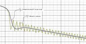
works as an R-C filter - while the cap sets the frequency we want to allow to pass (Pass seems to be omnipresent here...) the resistor sucks the life out of the passed noise signal. In stead of putting caps over the bridge rectifier diodes I put put the R-C combination over the positive rail and GND and mirrored it between the negative rail and GND just after the bridge. Below is a circuit with the results. This works extremely well for my small-casing amps where radiation noise is very unwelcome.
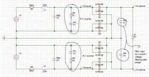
Notes on the circuit below: The circuit represents 2 secondary windings of a transformer giving AC voltage (V1 and V3). R5, R6, L1, L2 and C5 and C6 represents the transformer winding resistance, inductance and capacitance. These values depends on the transformer used and can be calculated. The frequency of the ringing generated depends on these values but are generally in the high kHz or even mHz. The R-C snubber combinations are R2 / C7 and R4 / C8. I chose these values because they will start damping out at fairly low frequencies and they are easilly available.
Please feel free to give your input - I think if the values are chosen correctly then it is a simple way to achieve a good purpose. If you guys can suggest alternative values for the R-C combination that would also help...
R-C "filters" are used in most amplifiers to set the roll-off frequency and help damp out high frequencies (mostly RF and transients). I figured that in a normal AC/DC amp PSU the frequency range we are most interested in are mains related (50/60 Hz or 120Hz for FWR) so anything higer could be unwanted.
Most of us have mains filtering put in before the bridge/s to filter out unwanted mains noise. After the bridge/s we have the larger ripple filter caps supplying the load with juices. Due to the internal impedance of these large caps (at high audio frequancies) we put in some bridging capse (1uF / 0.1uF) over these large caps.
The doides in the bridges introduce high frequency noise the moment they switch off. Although this switch-off noise can be lowered by using slow bridges and soft recovery type diodes there is still much unwanted noise generated by the bridges. Frequencies are in the high kHz region so, although not in the audio range, they cause havoc in the amp circuitry. It makes sense to give the amp only the frequency we want it to amplify rather than a whole bag full of noise to deal with while amplifying the stuff we want to listen to - even the balanced circuitry out there. Some "music" I've heard can be classified as noise, but we won't go there...!!! One day I'll build an amp that will filter out any "noise"... and nows how to be polight.)
So, we want to get rid of this noise added by the bridge/s. Actually the noise is not all the bridge diodes' fault, it's a combination of diode switching in a closed loop with an inductor (transofrmer coil) and some capacitance (transformer winding capacitance and diode C/A capacitance). Although these filter caps after the bridge deal with a lot of noise, the system can be improved by preventing the high frequency noise to generate in the loop before the bridge/s. It is not only the noise carried by the supply wires that get to the actual amplification circuitry but radiation also plays a huge role - especially at these high frequancies coupled through a nice "broadcasting" emmitter like
transformer coils... Using only caps are not good enough for high frequency snubbers. Jim's article explains how just a cap only lowers the high noise frequencies and does very little to snuff them out.
If we put in a resistor in series with the cap it works. This setup
works as an R-C filter - while the cap sets the frequency we want to allow to pass (Pass seems to be omnipresent here...) the resistor sucks the life out of the passed noise signal. In stead of putting caps over the bridge rectifier diodes I put put the R-C combination over the positive rail and GND and mirrored it between the negative rail and GND just after the bridge. Below is a circuit with the results. This works extremely well for my small-casing amps where radiation noise is very unwelcome.
Notes on the circuit below: The circuit represents 2 secondary windings of a transformer giving AC voltage (V1 and V3). R5, R6, L1, L2 and C5 and C6 represents the transformer winding resistance, inductance and capacitance. These values depends on the transformer used and can be calculated. The frequency of the ringing generated depends on these values but are generally in the high kHz or even mHz. The R-C snubber combinations are R2 / C7 and R4 / C8. I chose these values because they will start damping out at fairly low frequencies and they are easilly available.
Please feel free to give your input - I think if the values are chosen correctly then it is a simple way to achieve a good purpose. If you guys can suggest alternative values for the R-C combination that would also help...
Attachments
Hi Chirs,
Dissipation in the resistor is low as the line frequency is low. You can search this forum for Jim's article - there is a formula to calculate dissipation. You don't really have to go through all of that. I would suggest a 1W to be safe. If you choose your R-C values so that the frequency snubbed becomes too low the resistor W will have to increase. (I used 0.6W)
As the R-C setup is between your transformer secondaries and the bridge a fluctuating mains voltage should have virtually no effect on these values.
SV
for another step toward a low noise supply, put another RC on the secondary side and an inductor to feed the main caps.
simulate it, you will see greatly reduced stress on the diodes!
if you do that, you will also see that many designs overstress the diodes.
the resulting supply will have bad regulation, so it would be smart to put an active regulator on it.
well, this is what i'm planning for my next few amps, anyway.
Hi, vossie
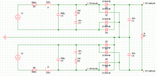
In your model diodes D1 and D5 are shortened, diodes D4 and D8 are useless (parallel with caps). If V1 has DC offset, than diode D2 is useless too, if V1 hasn't offset (only AC), than huge current will flow thru D2 (short generator connection for negative signal)( Same analysis for D8).
This model represent only half wave rectifier (one diode in each bridge is active ......... and make noise)
R7 must be smaller too.
IMHO
Regards
His only error is that
-the 2 secondaries are connected
-and they are connected to ground
remove the connection between the 2 secondaries, and theyr connection to ground
BTW, you seem to use simetrix. What kind of analysis did you perform? I didn't manage to get the same results as you
-the 2 secondaries are connected
-and they are connected to ground
remove the connection between the 2 secondaries, and theyr connection to ground
BTW, you seem to use simetrix. What kind of analysis did you perform? I didn't manage to get the same results as you
moamps - you're right, my apologies, the connection between the two primary windings should not be there and should be like the included pic.
Bricolo - I use Orcad Release 9 but re-did the schematic on a limited version of Simetrix as I did this on a laptop while away for business. Hence the screw-up with the schematic....
Best is to use a short step time (1u or so) and start looking recording data a bit later into the simulation. End result is still the same...
Attachments
- Status
- This old topic is closed. If you want to reopen this topic, contact a moderator using the "Report Post" button.
- Home
- Amplifiers
- Solid State
- PSU bridge snubber for RF noise