Hi,
I bought Genelec active speakers and would like to make a preout mod for my old amplifier Technics SA-DA8. The amplifier is a basic 5.1 home theater amplfier.
First of all, I have very little understanding of any aspects of modding electrical devices. So, please be patient with me.
What I have found so far, is that I should take the preamplified signal out from somewhere. Some thread suggested to take the signal after the potentiometer, which makes sense. I suppose there is a line going from the potentiometer to power amplifier for each channel. Right?
If I manage to do this, the next thing I read is that I should match the output impedance of the preamplified section of my amplifier to Genelecs input impedance, which is 10kOhm. It is a still unclear for me, what electrical component should I use to make impedance match. What is considered a good match? What would be a recommended solution? Moreover, I don't know how to measure the output impedance of the amplifier. Is there any easy approximate way?
Is there anything else I should know?
Thank you for any help.
-Tony
Does your Technics even have a potentiometer for volume or is it "electronic" using a rotary encoder with the attenuation being achieved electronically.
It would be very easy to cause damage if you are not experienced. If you have a service manual we would be better placed to advice where to take a feed from if possible.
One possible solution is just to fit a resistive divider across the left and right speaker outputs (done externally to the amp) and to take a feed from there.
Hey,
Thanks for the answers.
I expect there is an actual potentiometer, but I'll check that out tomorrow.
I found a service manual for the amplifier:
koti.mbnet.fi/photony/technics_sa-da8.pdf
I also found a more extensive manual for Technics SA-DA10, which is essentially the same amplifier
koti.mbnet.fi/photony/technics_sa-da10.pdf
I gave a thought for making a buffer to use with the Genelecs. However, if this preout mod works, I have one needless amplifier less in the circuit. Plus, this is a nice and hopefully fun my first diy audio project =)
-Tony
I was trying to repair a bad volume pot on a transistor radio yesterday and discovered it has a single resistor volume pot for a "stereo" radio. This is a pretty good tip-off that the pot is providing an input to the IC, and the attenuation is being done in the IC on the two channels. Real volume pots have as many resistors as the device has output channels.
Hi,
Sorry about the links. I should have put http:// in front of the addresses. Here are working ones. Those are quite big files, so it might take a while for the download to finish.
SA-DA8 (3mb)
http://koti.mbnet.fi/photony/technics_sa-da8.pdf
SA-DA10 (7mb)
http://koti.mbnet.fi/photony/technics_sa-da10.pdf
I found from the schematics that there are 3, not 5 or 5.1, electronic volume adjusters in the circuit. Maybe there is some similar circuit to Indianajo's radio explaining the number of the adjusters. Not sure if they are the master volumes though. I think I also found a potentiometers sign, with all channels connected in the circuit. Again, not sure if it's the master volume or not.
I'll open the amplifier today, and try to learn something.
-Tony
Last edited:
Talk about minimalist audiophile approach ")
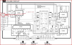
It does appear to have a "normal" (if you call 6 gang normal) control.
L and R audio should be available where I marked on the diagram. It's from a low impedance opamp source so no problems driving other loads and it appears to be a separate PCB too. If you do tap into this then I would feed into a 100 ohm resistor and 10uf series cap terminated to ground via a 100K.
Attachments
Hello Photony,
Are you confident doing this? I think this is the real question- You sounded a bit hesitating in your first post. If you are by any means try Mooly's suggestion. It will get you going. It will not , i suspect, get the most of your Genelecs. I don't know which model you have, but 1031A 's were *very* responsive to preamp changes.
Have fun experimenting,
T.
PS, make sure you have a good adaptor cable (RCA>XLR) and keep it short, mains cable proved to be sensitive too, but the latter is fine tuning. However, when all else is sorted out, it makes for a surprising difference for the better - just DIY!
Hi there,
Thank you for the replies. Especially thanks to Mooly for pointing out the spots in the circuit. I opened the amplifier yesterday and had the opportunity to do some measurements with the guidance of my friend.
First of all I found the spots Mooly pointed out. I also did voltage measurement with signal generator and oscilloscope from these spots. The result was:
Input: 0.5V peak to peak
Output: 4V peak to peak @ 50% of max volume
We were in a little hurry and I forgot to make the impedance measurement. I think it should have been also good to measure the maximum output voltage. Had a slight problem with that measurement since it burned the resistor connected to the normal speaker output terminals. Didn't have a better resistor available. The resistor was needed because otherwise there was no signal coming through. The potentiometer seemed to be logarithmic so I would suspect turning the volume to max giving me 16 volts though.
I still have some questions for you if you don't mind =)
1. Do you think I should make the impedance and max output measurement?
2. Mooly, is the measured output something you anticipated? If not, does the circuit you suggested need some modifications?
3. My friend also suggested to make a voltage follower for each channel by using operational amplifiers. The reason was to avoid causing interference with the amplifier itself. Do you think this is necessary?
This has been fun so far. Learned a lot of things. I don't expect this to be a optimal solution for my Genelecs, but currently the Genes are connected straight to my TV. It's hard not to improve from that =)
-Tony
You need to specify where you are measuring the voltages. Not sure if your output voltages are on the speaker terminals or the points marked on circuit.
The points I did mark on the circuit are fed directly from an opamp output so there will be no problem feeding your active speakers from here. The output impedance at this point is very low << 1 ohm and will fully drive loads from around 1K upwards, so no problem. A follower isn't needed. You need a feed as I described earlier with a small isolation resistor (to ensure stability of any capacitive loading due to cable and input circuit of speakers) and a cap to ensure 0.00 volts DC at all times (that's just good practice) and a 100 k to tie that cap to ground (again good practice).
If you do test power amp output voltages then, as you know the amp is OK there is no real point testing with dummy loads. The open circuit voltage will be essentially the same.
Hi,
This sounds great! If I understood correctly from your response Mooly, the ratio "input impedance of the speaker / output impedance of the amplifier", should be large. The Genelecs input impedance was 10Kohm so this sounds good if already 1Kohm is sufficient.
About my earlier message. I made the measurements between the points you marked on the circuit and ground. Should've pointed that out.
I guess I'm all set to go. Thanks again. I'll let you know how everything goes.
-Tony
Last edited:
Hi,
I just finished with the preout mod. Yeah =) It seems to work, but only when I have an analog source. I get sound from digital sources, but only when using speaker terminals. Not from the points Mooly pointed out at the pcb in his attached picture.
At this point it's hard to say about the sound quality, since the digital signal is decoded in tv and fed through RCA cable to the amplifier.
So, any ideas what is causing that there is no signal when using a digital source? And how to fix it? Thanks for any help,
Tony
From what you describe it sounds as though the digital audio in some way bypasses the opamp points I marked on the circuit...
Not having a paper manual where it can all be spread out makes tracing the ausio path difficult.
What I would do is first confirm by scope that there is no audio at the points I marked when listening to a digital source (you mean like SPDIF input ?) I find it strange if there is not audio there on a digital input as that would point to two "volume controls", one operating in the digital domain and one in analogue.
Depending on that result I would start at the power amps for left and right front main channels (or headphone output could be a possibility too) and trace the audio back physically using scope and circuit to refer too and see where that leads you.
Hi Mooly,
Thanks for the tips. I haven't had the change to test those yet.
I'm wondering could this be some kind of resistance or grounding issue. My guess is based on that I discovered that there had to be a resistor in the speaker terminals to get a signal to the oscilloscope from the points you marked. There, however, is a signal also without the resistor if I have the active speakers connected to those points. I would say the reason is that the active speakers generate enough resistance for the circuit to activate.
So, could this be a similar phenomenon: When the analog input is active, the circuit gets ground or resistance while there is something different when the signal is from the dac?
-Tony
That sounds strange tbh.
You need your scope ground connected to the "audio ground" in the amp which is pin 8 of CP451 in the picture in post #8
I would expect to then see audio on pins 1 and 7 of IC 503 that varies with the volume setting. You need to try that and with a variety of inputs.
You need your scope ground connected to the "audio ground" in the amp which is pin 8 of CP451 in the picture in post #8
I would expect to then see audio on pins 1 and 7 of IC 503 that varies with the volume setting. You need to try that and with a variety of inputs.
Hi,
Still haven't got the change to do measurements. Unfortunately, I don't have my own test equipment.
I recall that I have tested the ground I have used against the pin 8 Mooly pointed out. I got zero, but then again, there was analog signal input when I tested it. So, there is a slight possibility that the grounding point makes a difference.
I'm now considering to take the signal out just before the power amplifiers. How this sounds? At least the signals are merged before that point plus all the possible adjustments to the signal are made before that stage. Is there some obvious disadvantages?
There are three two channel (class H+) power amplifiers. In the schematics
http://koti.mbnet.fi/photony/technics_sa-da10.pdf
they are on the page 113 IC601, IC602 and IC651. One of the six channels is unused. In the schematics, there are also boxes containing text L.P.F and H.P.F. I believe these are low and high pass filters. I probably should figure out if I should or should I not to use the filters.
-Tony
Can't get your pdf to download correctly for some reason.
To take the signal from the power amp inputs for the main speakers is the correct place signal content wise, and that was what I was trying to trace back on the other circuit in previous links. The correct ground only really matters in ensuring that there is no interference or hum and so on. Complex circuits like this have several grounds... they all read "zero ohms" one to another but use the wrong one and the audio will suffer, maybe audibly.
You can't beat a paper manual for things like this where you can spread it all out in front of you
- Status
- This old topic is closed. If you want to reopen this topic, contact a moderator using the "Report Post" button.
- Home
- Source & Line
- Analog Line Level
- Preout mod