I designed and built this inrush limiting board and installed it in my Pimped Citation 16 power amp project. It has by now worked flawlessly for more than a year since the installation. Despite the principle of the simple the better, I figured many amp DIYers may actually interested in an inrush limiting design that does a little more than just limiting the inrush current. My design offers the following:
1. limiting inrush to a 1KVA toroid and 80,000uF on 55Vdc, can be scaled up or down.
2. supporting lighted momentary push button switch as power switch
3. reservoir cap charge-up detection
4. power-good monitoring with under voltage shutdown
5. built-in speaker relay driver operating upon power-good condition
6. allowing external controls to cutoff speaker relays (working with speaker terminal DC detection, for example)
7. Header for off-board relays if on-board relay installation is not desired.
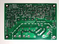
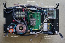
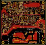
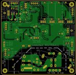
Schematic diagram and pictures of PCB are attached. Unfortunately I lost the pictures of PCB with populated parts on. Pictures of the installed PCB in my amp can be found at the link below:
http://www.diyaudio.com/forums/solid-state/170892-i-pimped-my-citation-sixteen-resurrected.html
A short video clip about the power switch in action, toe-operated:
MOV02729 | Flickr - Photo Sharing!
I don't know a better way to describe how it works so I simply spread it out in words:
This circuit is based on hard-wired logic/timer devices, it controls the mains power relays and speaker relays. It works on a 12VDC secondary supply.
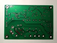
The circuit was laid out on a two-sided PCB that requires some basic SMD soldering skills to assemble.
The circuit works with a lighted push-button switch with momentary contacts as the power switch, each push starts a 5-second time window during which the switch itself is disabled and the lamp flashes.
When starting from standby the soft-start relay will engage for as long as the time window lasts (5s), the mains power is applied through three GE CL-40 NTC thermister in series (15 ohms in total at room temperature). This will limit the inrush current and charge up the main caps in a controlled manner.
The main caps should be charged up well within the 5-s time window and the rail voltage flats out. A flat-out detection circuit will engage a power-good monitor and if a power-good status is positive the circuit enters power-on mode, the main relays (two in parallel) will bypass the inrush limiter and connect the primary winding of the power transform directly to the mains supply, the lamp in the power switch stops flashing to glow at a normal brightness, the speaker relays will also engage at the same moment given that there are no external controls that prohibit it. The soft-start relay then cuts out at the end of the 5-s time window.
If no power rail flat-out is detected or no power-good is established during the 5-s time window, the main relays and the speaker relays will not engage, and the circuit returns to standby mode at the end of the time window, the lamp in the power switch then stops flashing to glow a dim light.
Pushing the power switch during power-on mode will simply disengage power relays and speaker relays, and a 5-s time window follows to, if equipped with a discharger, allow the main caps to be discharged deeply enough prior to responding next button push.
The PCB size is 100mm X 69.5mm and should yield quite well in a 18"X24" panel for 32 pieces.
I'm thinking if there is certain interest we may be able to do a group buy, and this design could be enjoyed by more than one.
1. limiting inrush to a 1KVA toroid and 80,000uF on 55Vdc, can be scaled up or down.
2. supporting lighted momentary push button switch as power switch
3. reservoir cap charge-up detection
4. power-good monitoring with under voltage shutdown
5. built-in speaker relay driver operating upon power-good condition
6. allowing external controls to cutoff speaker relays (working with speaker terminal DC detection, for example)
7. Header for off-board relays if on-board relay installation is not desired.
Schematic diagram and pictures of PCB are attached. Unfortunately I lost the pictures of PCB with populated parts on. Pictures of the installed PCB in my amp can be found at the link below:
http://www.diyaudio.com/forums/solid-state/170892-i-pimped-my-citation-sixteen-resurrected.html
A short video clip about the power switch in action, toe-operated:
MOV02729 | Flickr - Photo Sharing!
I don't know a better way to describe how it works so I simply spread it out in words:
This circuit is based on hard-wired logic/timer devices, it controls the mains power relays and speaker relays. It works on a 12VDC secondary supply.
The circuit was laid out on a two-sided PCB that requires some basic SMD soldering skills to assemble.
The circuit works with a lighted push-button switch with momentary contacts as the power switch, each push starts a 5-second time window during which the switch itself is disabled and the lamp flashes.
When starting from standby the soft-start relay will engage for as long as the time window lasts (5s), the mains power is applied through three GE CL-40 NTC thermister in series (15 ohms in total at room temperature). This will limit the inrush current and charge up the main caps in a controlled manner.
The main caps should be charged up well within the 5-s time window and the rail voltage flats out. A flat-out detection circuit will engage a power-good monitor and if a power-good status is positive the circuit enters power-on mode, the main relays (two in parallel) will bypass the inrush limiter and connect the primary winding of the power transform directly to the mains supply, the lamp in the power switch stops flashing to glow at a normal brightness, the speaker relays will also engage at the same moment given that there are no external controls that prohibit it. The soft-start relay then cuts out at the end of the 5-s time window.
If no power rail flat-out is detected or no power-good is established during the 5-s time window, the main relays and the speaker relays will not engage, and the circuit returns to standby mode at the end of the time window, the lamp in the power switch then stops flashing to glow a dim light.
Pushing the power switch during power-on mode will simply disengage power relays and speaker relays, and a 5-s time window follows to, if equipped with a discharger, allow the main caps to be discharged deeply enough prior to responding next button push.
The PCB size is 100mm X 69.5mm and should yield quite well in a 18"X24" panel for 32 pieces.
I'm thinking if there is certain interest we may be able to do a group buy, and this design could be enjoyed by more than one.
Attachments
Last edited:
Is it suited to 240V mains for those who live in English speaking countries?")
Never tried, but I would say yes as a quick answer though some minor changes and experiments may be necessary. The thermistors, for example, may better be a different value (doubled perhaps) in order to yield a proper inrush current intended, as well as to keep the charge up time of the reservoir capacitors within 5 seconds. Charge-up time of longer than 5 seconds will result in no turn-on, and the circuit will always return to standby mode when the 5-second time is up.
The primary-secondary spacing on the PCB is 8mm minimum, Live-Neutral spacing is 2.5mm minimum, the primary side has a 4mm minimum distance to the board edges, I'm not certain if these numbers go along with the codes in all 240V English speaking countries, also uncertain is the quick-on type connectors on the mains leads being allowed in all countries, although they should be good to my knowledge.
The on-board relays I use seem to be okay as they are rated at 12A/250Vac.
The PCB has a name now -- GENTLON
After a few successful builds and trouble-free operation for a few years, I decided to revise the PCB to include its own PSU, 4-channel DC rail monitor, two each positive and negative, and a 4-channel reservoir cap automatic discharger. It has headers to accept external power shutdown and speaker shutdown override controls too. Basically what are on the 4 PCBs in the Meistersinger amp, shown in the last post, now are on one PCB. The board is now 10x10 cm^2, still qualified at many PCB shops for least expensive prototype pricing.
After a few successful builds and trouble-free operation for a few years, I decided to revise the PCB to include its own PSU, 4-channel DC rail monitor, two each positive and negative, and a 4-channel reservoir cap automatic discharger. It has headers to accept external power shutdown and speaker shutdown override controls too. Basically what are on the 4 PCBs in the Meistersinger amp, shown in the last post, now are on one PCB. The board is now 10x10 cm^2, still qualified at many PCB shops for least expensive prototype pricing.
Attachments
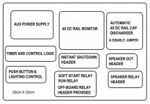
GENTLON schematic and layout
Layout is done on a double sided PCB, all SMD components on one side, and all through-hole parts on the other. Stacking with an additional board will be easy for additional sensory or control circuit.
Layout is done on a double sided PCB, all SMD components on one side, and all through-hole parts on the other. Stacking with an additional board will be easy for additional sensory or control circuit.
Attachments
- Status
- This old topic is closed. If you want to reopen this topic, contact a moderator using the "Report Post" button.