Hello,
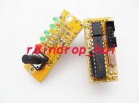
I have finally installed an wm8805 upgrade board - pin compatible with CS8414 and find the results inconclusive.
Ebay:
WM8805 Digital receiver, CS8412 CS8414 converter module | eBay
Other than minor malfunctions of switching circuits, the borad is 'working' but I can't distinguish any remarkable sound improvements.
I happen to have 2 dacs and compared the sound with the stock cs8414 dac. Both sound good. My transport is a cheap LG DVD player, so I would assume there should have been an improvement.
The minor malfunctios of this kit:
1. Led indicating input source (4 of them) don't light up
2. The switch that is supposed to change the outpout mode (i2s 16bit, i2s 24bit, etc) does not have an effect on the associated LED's indication the actual output mode, hence not working
3. Missing error pin on pin 25 of original cs8414 (my dac used this for an led).
It looks like the circuit does not use the crystal option on the wm8805, maybe that would improove performance?
Maybe it would have been easier to build this from scratch, assuming the WM8805 can output i2s 24bit in hardware mode (as most of it's settings are only available in software mode)
Also my Dac has a 'buffer' on the spdif input, not sure that would affect negatively the wm8805.
Any thoughts?
Attachments
Hi, WM8805 needs a 12 MHz clock for operation which includes dejittering the incoming signal. This function is one of the features that make this chip stand out from the rest. It certainly is way better than CS8412 or CS8414. All this together with the issues you mention make me think you have a crappy designed device. It is definitely not the chip that is disappointing I can tell.
Maybe you can ask the seller for a schematic ? BTW except for item #3 I would call the "minor malfunctions" major malfunctions as the device obviously does not work as advertised. It is defective.
Maybe you can ask the seller for a schematic ? BTW except for item #3 I would call the "minor malfunctions" major malfunctions as the device obviously does not work as advertised. It is defective.
Last edited:
Thanks for the info. I was expecting improvments even without the external 12MHz crystal as the intristic jitter of the device in 50ps and PLL clock recovery and de-jitter using a buffer can be quite effective. The crystal 8414 has 200ps of intristic jittter, so no matter how good the input or de-jittering pll, the device can contribute its own 200ps.
In terms of starting from scratch my concern is that thw WM8805 requires software register settings for i2s output among other things, and that can get complicated, hence the Atmel cpu on the chineese board. The WM88805 Data Sheet is not clear about this.
In terms of starting from scratch my concern is that thw WM8805 requires software register settings for i2s output among other things, and that can get complicated, hence the Atmel cpu on the chineese board. The WM88805 Data Sheet is not clear about this.
Last edited:
Send it back to the seller and ask for a working one is what I would do first. If the new one works OK I would add a 12 Mhz clock (if it has none).
It can be simple sometimes") You can't expect improvements when the chip is not used correctly or when the design has flaws. Are you sure the WM8805 Xin pin is not connected ?
You can't expect improvements when the chip is not used correctly or when the design has flaws. Are you sure the WM8805 Xin pin is not connected ?
It can be simple sometimes
You can't expect improvements when the chip is not used correctly or when the design has flaws. Are you sure the WM8805 Xin pin is not connected ?
Last edited:
Other than minor malfunctions of switching circuits, the borad is 'working' but I can't distinguish any remarkable sound improvements.
I happen to have 2 dacs and compared the sound with the stock cs8414 dac. Both sound good. My transport is a cheap LG DVD player, so I would assume there should have been an improvement.
I have quite a few cheap DVD players (unknown Chinese brands). Their SMPSUs are fairly noisy and the noise carried through the SPDIF cable into the DAC is the main reason for sound degradation. If you want to improve the sound you're getting, improve the grounding of the SPDIF input of your DAC rather than swapping out the SPDIF receiver.
Isolation transformers only isolate perfectly at DC. Do you know the interwinding capacitance of your transformer? It would still pay to ensure that the ground side of the trafo output doesn't share any common ground impedance with the audio outputs.
<edit> Ooops, misread your post and assumed you'd added the trafo on the input. Sorry about that. A trafo on the SPDIF output can still couple noise, depending on the interwinding capacitance.
<edit> Ooops, misread your post and assumed you'd added the trafo on the input. Sorry about that. A trafo on the SPDIF output can still couple noise, depending on the interwinding capacitance.
I recently bought this one, from the same designer:
DAC TDA1543*4+WM8805 NOS USB, Optical, Coaxial input | eBay
Had no problems at all with the WM8805 and software, just the grounding (hence sound) sucked until I rewired it Now it sounds jolly sweet, even fed from a 199rmb DVD player.
DAC TDA1543*4+WM8805 NOS USB, Optical, Coaxial input | eBay
Had no problems at all with the WM8805 and software, just the grounding (hence sound) sucked until I rewired it
Now it sounds jolly sweet, even fed from a 199rmb DVD player.Raindrop_hui I think is the name of the seller - she lives in Shandong province. The designer/builder though is just a stone's throw from me, halfway to Shanghai. 'Hui' has many meanings in Chinese, the only meaning I know about is 'know' as in 'I know how to speak Chinese' (which I don't
).Hi, WM8805 needs a 12 MHz clock for operation which includes dejittering the incoming signal.
Can you show EXACTLY where it is stated that that clock helps "dejittering"?
Because the data sheet says that PLL loop is used to extract the sample rate and the output frequency will follow the input one. There is no mentioning of any "dejittering".
The crystal just provides the free-running frequency of the PLL loop and also helps detecting the value of the incoming samplerate and signaling it further.
There should be no ferrite bead between the grounds. Grounds are tied toghether INSIDE the DAC anyway. Only beads on positive rails makes a difference.Grounding is an interresting subject. On my dac-38 digital ground is connected to analog ground in one signgle location via a ferrite jumper.
Last edited:
Grounding is an interresting subject. On my dac-38 digital ground is connected to analog ground in one signgle location via a ferrite jumper.
I wonder why they used a ferrite bead for that connection? I presume the digital and analog supplies come from separate windings on the mains trafo? If so then there's at least one loop for RF via the interwinding capacitance of the transformer.
What's the best ground philisophy on a dac?
Same as the best grounding philosophy for an amp, pre or whatever. Rigorous star grounding to ensure (especially) that no digital, switching supply-related or mains hash currents get superimposed on the analog audio outs.
<edit> @Pano - I remembered after writing the earlier post that one of the other meanings of 'hui' in Chinese is 'community' - so perhaps Chinese and Hawaiian aren't so far apart after all.
Last edited:
Can you show EXACTLY where it is stated that that clock helps "dejittering"?
Because the data sheet says that PLL loop is used to extract the sample rate and the output frequency will follow the input one. There is no mentioning of any "dejittering".
The crystal just provides the free-running frequency of the PLL loop and also helps detecting the value of the incoming samplerate and signaling it further.
There should be no ferrite bead between the grounds. Grounds are tied toghether INSIDE the DAC anyway. Only beads on positive rails makes a difference.
OK, it is the internet age and OK data sheets are sometimes hard to read but in this case: first page of the data sheet, first sentences under "description". Not info I "heard", "thought", "assumed" or "googled" . No, just reading the data sheet as we all did once before we made any statements. Contrary to other chips and old knowledge this one is quite sensitive on the quality of the used 12 MHz clock despite its PLL. Best is to use a low jitter XO and not simply a crystal.
While you are at it please check the whole data sheet and see why this chip is ahead of its competitors. Also the standard schematic works quite good. Using even less parts than in the standard schematic will not guarantee the features as described.
I don't work for Wolfson or something like that. It is just that they designed a very good chip which easily outperforms all other SPDIF receivers made till now that I know of.
Last edited:
Hi,
The WM8805 CANNOT work without a crytsal or clock somewhere. This clock is critical in terms of PSU noise.
Yes, it will. The inputs on the 8805 expects SPDIF levels, you need to switch it (in software) to CMOS levels if you want to feed these.
Further, looking at your DAC, I am unsurprised that there is no appreciable improvement, given the design as it is.
One of the main "on board" jitter generators (the digital filter) is not addressed by re-clocking and many of circuit choices are extremely dubious, including the apparent lack of any competent HF decoupling for digital circuitry. To me this DAC appears like a ruddy waste of a rather decent chipset.
Ciao T
It looks like the circuit does not use the crystal option on the wm8805, maybe that would improove performance?
The WM8805 CANNOT work without a crytsal or clock somewhere. This clock is critical in terms of PSU noise.
Also my Dac has a 'buffer' on the spdif input, not sure that would affect negatively the wm8805.
Yes, it will. The inputs on the 8805 expects SPDIF levels, you need to switch it (in software) to CMOS levels if you want to feed these.
Further, looking at your DAC, I am unsurprised that there is no appreciable improvement, given the design as it is.
One of the main "on board" jitter generators (the digital filter) is not addressed by re-clocking and many of circuit choices are extremely dubious, including the apparent lack of any competent HF decoupling for digital circuitry. To me this DAC appears like a ruddy waste of a rather decent chipset.
Ciao T
If you would read PAST the first page (that page is just a advertisement of the product), you will found out when output is PLL derived (always in receiver mode), wgen is derived from a digital interface incoming clock (transmitter mode) and when is purelly Xtal derived (never).first page of the data sheet, first sentences under "description".
Is like I quoted above - from page 21: "whenever the SPDIF receiver is ENABLED, it generates the clock for the PLL".
So, in the RECEIVEING mode, the output is tied to the input via PLL. It cannot work otherway.
When is used as a TRANSMITTER, then it requires an external source for clock reference (from the digital audio source).
NOWHERE on the rest of the data sheet is explained how that "dejittering" is done. Or if.
PS: They even give the same 50pS jitter as DIR9001. So they are better only compared with CS receivers (at 200pS).
Last edited:
Hi,
Actually, reading the WHOLE datasheet and understanding it would reveal that the clock is ALWAYS PLL derived when the WM8805 is clock master and that the PLL is a DPLL that uses the WM8805 Clock, this holds true for SPDIF receiver mode, transmitter mode and pass-trough mode.
In receiver mode the programming of the DPLL's output is controlled by the SPDIF receiver through a control logic that is derived from a FIFO buffer's fill state via a DSP lowpass filter which stands at 100Hz once locked, while in transmitter mode it is controlled in software.
In transmitter mode you CAN run the system on external clocks only, assuming your clock generator is much better than what is inside the WM8805.
As for the 50ps, a programmable clock using a DPLL has limits, as it synchronises a RC oscillator derived clock with the external reference clock by using a fractional divider. The 50ps are for typical applications.
The WM8805 has the PLL Clocks supply pins separately available so any noise here can be minimised by appropriate design and the reference clock can be supplied by a oscillator with arbitrary low jitter, so practical implementations can measure much worse than the 50pS jitter, it is also possible to do quite a bit better.
Secondly, the XXXpS specified for all receivers assume a source without jitter. Real sources easily clock in at several nanoseconds jitter, so much more crucial is the rejection of baseband jitter... As long as the jitter is of a level and frequency that can be rejected by the receiver and the design is competent, the specified jitter will be reached, if the jitter is of a frequency and level that cannot be filtered completely jitter will be increased over specification.
That said, given that ALL other receivers on the market have their source jitter rejection turnover at 10KHz or higher one could say that the WM880X is 100 times better than anything on the market.
Still, it is possible to do much better than the WM880X does, with respect to jitter, however it does need quite complex solution and fairly large amounts of memory.
My biggest dislike for the WM8805 is that it's external control interface to any MCU is extremely riddled with "undocumented features" (unlike the AKM Parts) and that 176.4KHz operation is unavailable in "standalone mode" (unlike the AKM Parts), so you MUST use an MCU no matter what.
Another gripe of mine is that it lacks a provision of "sideport" memory which would allow the corner frequency of the source jitter rejection to be lowered from 100Hz to 10z or even below 1Hz.
With AKM parts (and others) other solutions are needed to reject source jitter sufficiently of course.
The Cirrus Logic Parts tend to have so many bugs early on in their lifecyle, they are best avoided in self defence and TI/BB's receivers seem to do at least as bad...
Ciao T
If you would read PAST the first page (that page is just a advertisement of the product), you will found out when output is PLL derived (always in receiver mode), wgen is derived from a digital interface incoming clock (transmitter mode) and when is purelly Xtal derived (never).
Actually, reading the WHOLE datasheet and understanding it would reveal that the clock is ALWAYS PLL derived when the WM8805 is clock master and that the PLL is a DPLL that uses the WM8805 Clock, this holds true for SPDIF receiver mode, transmitter mode and pass-trough mode.
In receiver mode the programming of the DPLL's output is controlled by the SPDIF receiver through a control logic that is derived from a FIFO buffer's fill state via a DSP lowpass filter which stands at 100Hz once locked, while in transmitter mode it is controlled in software.
In transmitter mode you CAN run the system on external clocks only, assuming your clock generator is much better than what is inside the WM8805.
As for the 50ps, a programmable clock using a DPLL has limits, as it synchronises a RC oscillator derived clock with the external reference clock by using a fractional divider. The 50ps are for typical applications.
The WM8805 has the PLL Clocks supply pins separately available so any noise here can be minimised by appropriate design and the reference clock can be supplied by a oscillator with arbitrary low jitter, so practical implementations can measure much worse than the 50pS jitter, it is also possible to do quite a bit better.
Secondly, the XXXpS specified for all receivers assume a source without jitter. Real sources easily clock in at several nanoseconds jitter, so much more crucial is the rejection of baseband jitter... As long as the jitter is of a level and frequency that can be rejected by the receiver and the design is competent, the specified jitter will be reached, if the jitter is of a frequency and level that cannot be filtered completely jitter will be increased over specification.
That said, given that ALL other receivers on the market have their source jitter rejection turnover at 10KHz or higher one could say that the WM880X is 100 times better than anything on the market.
Still, it is possible to do much better than the WM880X does, with respect to jitter, however it does need quite complex solution and fairly large amounts of memory.
My biggest dislike for the WM8805 is that it's external control interface to any MCU is extremely riddled with "undocumented features" (unlike the AKM Parts) and that 176.4KHz operation is unavailable in "standalone mode" (unlike the AKM Parts), so you MUST use an MCU no matter what.
Another gripe of mine is that it lacks a provision of "sideport" memory which would allow the corner frequency of the source jitter rejection to be lowered from 100Hz to 10z or even below 1Hz.
With AKM parts (and others) other solutions are needed to reject source jitter sufficiently of course.
The Cirrus Logic Parts tend to have so many bugs early on in their lifecyle, they are best avoided in self defence and TI/BB's receivers seem to do at least as bad...
Ciao T
@ThorstenL:
Correct. Some people tend to attribute "magic" powers to pices of silicon just based on their guesses, instead of really reading the datasheets. They see that Xtal and they ASSUME that the output will have that Xtall stability. That's what WM wanted for them to belive too, that's why that wrote that first page like that.
As for the FIFO buffer inside the WM8805 - I think that is not present. They have that white paper that seems to indicate that, but that's it. Inside the 8805 there is no mention of a FIFO buffer. And surelly not one that can handle 20 ms of audio data (at 24bit/192kHz) needed for what they claim to do (100Hz corner).
It is just about using a lower-pass filter PLL. And that works great with good sources (but any receiver will work well then), but can lead to some frequency-following distortions for a source with higher jitter.
Last edited:
Hi,
Well, whatever is in there does appear to work in practice like what they claim (according to AP Sys 2722).
Also, you do not need 20mS buffer for 100Hz corner for jitter rejection at several UI (or nanoseconds) worth of jitter, you would be surprised how short such a buffer could really be to get this result.
The problem is of course, you cannot actually do that. As Cirrus logic found out in their CS8416 when it had around 10 times of the jitter of the earlier parts, it does not work as you might think it does.
Ciao T
As for the FIFO buffer inside the WM8805 - I think that is not present. They have that white paper that seems to indicate that, but that's it. Inside the 8805 there is no mention of a FIFO buffer. And surelly not one that can handle 20 ms of audio data (at 24bit/192kHz) needed for what they claim to do (100Hz corner).
Well, whatever is in there does appear to work in practice like what they claim (according to AP Sys 2722).
Also, you do not need 20mS buffer for 100Hz corner for jitter rejection at several UI (or nanoseconds) worth of jitter, you would be surprised how short such a buffer could really be to get this result.
It is just about using a lower-pass filter PLL.
The problem is of course, you cannot actually do that. As Cirrus logic found out in their CS8416 when it had around 10 times of the jitter of the earlier parts, it does not work as you might think it does.
Ciao T
- Status
- This old topic is closed. If you want to reopen this topic, contact a moderator using the "Report Post" button.
- Home
- Source & Line
- Digital Line Level
- WM8805 upgrade board (cs8414 pins) - dissapointed