I'm just getting started with designing and building circuits. One of my first projects is a CMoy headphone amp. The amp itself is simple enough, and I'm completely comfortable with it. But, I have a single pole power switch I'd like to use (for aesthetic reasons), and I'm stuck on how I can use this to switch both the + and - rails.
My topology and self-imposed design constraints:
- There will be a small toroidal transformer providing 9-0-9 AC. This will be rectified and feed 7806 and 7906 linear regulators. (+/-6 because I already have a pair of them and when will I ever need 6V?)
- I could just switch the transformer primary, but the switch will be on the front panel next to the volume knob, and I'd like to keep the mains and audio as far apart as possible.
- The actual circuit of course is pretty much an OPA2134 and an LED, plus the loss in the regulators. 100mA is probably a generous target. The whole thing could just run continuously, but as both a learning exercise and as good form, I'd like to only power the load while in use. Preferably, switching before the regulators.
- I don't want to use relays. It's going in a small case (of course), and I'd like to use this as an opportunity to learn more about transistors.
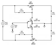
Ideally, I would have the rectified +9 run through the switch, and have it saturate a pair of MOSFETs -- one for each rail. Something like this, where the 1k resistors represent a load:

I have a couple spare MTP3055s (NPN) on-hand, so switching the positive rail is easy. What I don't know is how best I could use that same +9 to turn on the negative rail.
In the Falstad simulator (from which the image was taken), current runs through the negative MOSFET regardless of the switch. I confess, I don't really know why -- maybe just a fluke in the simulation of ground?
I'm sure this is a really basic problem that has been covered a million times before. I just don't know where to look. I could use an opamp as a comparator, but it seems a bit foolish to use an opamp to switch on another opamp! There's gotta be an easier way...
I appreciate any ideas or suggestions.
My topology and self-imposed design constraints:
- There will be a small toroidal transformer providing 9-0-9 AC. This will be rectified and feed 7806 and 7906 linear regulators. (+/-6 because I already have a pair of them and when will I ever need 6V?)
- I could just switch the transformer primary, but the switch will be on the front panel next to the volume knob, and I'd like to keep the mains and audio as far apart as possible.
- The actual circuit of course is pretty much an OPA2134 and an LED, plus the loss in the regulators. 100mA is probably a generous target. The whole thing could just run continuously, but as both a learning exercise and as good form, I'd like to only power the load while in use. Preferably, switching before the regulators.
- I don't want to use relays. It's going in a small case (of course), and I'd like to use this as an opportunity to learn more about transistors.
Ideally, I would have the rectified +9 run through the switch, and have it saturate a pair of MOSFETs -- one for each rail. Something like this, where the 1k resistors represent a load:
I have a couple spare MTP3055s (NPN) on-hand, so switching the positive rail is easy. What I don't know is how best I could use that same +9 to turn on the negative rail.
In the Falstad simulator (from which the image was taken), current runs through the negative MOSFET regardless of the switch. I confess, I don't really know why -- maybe just a fluke in the simulation of ground?
I'm sure this is a really basic problem that has been covered a million times before. I just don't know where to look. I could use an opamp as a comparator, but it seems a bit foolish to use an opamp to switch on another opamp! There's gotta be an easier way...
I appreciate any ideas or suggestions.
Thanks for the replies, everyone.
I've tried putting SofaSpud's idea in my simulator, and I can't get it to work right -- yet. I'm not sure if I'm doing something wrong, or running into bugs or limitations in the simulator. (It's designed as an educational tool to tinker with -- not a design tool -- and I've found at least one confirmed bug so far.) I'm still plugging away at it, and getting a feel for how to use the various parts (N- vs P-channel, etc.) along the way. If anyone has suggestions for free or cheap sims that are (relatively) friendly to beginners, I'd love to hear about them.
I'll try the second idea, too. I had a fleeting thought to try switching the ground, but had not quite come up with the hows and wheres yet. Thanks for that.
@preiter: Concerns duly noted. Even if I do switch the incoming AC, I have live mains all the way to the switch at least -- which will be on the opposite end of the case from the inlet. Instead, if I have the mains side of the transformer unswitched, but completely within the rear few inches, I can shield it with a box-within-a-box to keep that portion isolated -- for both noise control and safety.
Free simulator
There is a free version of Tina SPICE-Based Analog Simulation Program available on the TI website.
SPICE-Based Analog Simulation Program - TINA-TI - TI Tool Folder
There is a free version of Tina SPICE-Based Analog Simulation Program available on the TI website.
SPICE-Based Analog Simulation Program - TINA-TI - TI Tool Folder
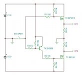
I think raudio's design will do the trick. I need to order some P-channel MOSFETs before I can breadboard it, but the simulation is working great. (I've got to get up to speed on the SPICE modeler, so I'm still using the Falstad sim for now.)
I'm not sure what VF is supposed to stand for, so I'm guessing R5 and R6 are still representative of the load, and VF1 and 2 are probe points? Is that right, or do R5 and R6 serve some other subtle purpose, while VF1 and 2 are outputs? The rest of it makes perfect sense to me.
I'm not sure what VF is supposed to stand for, so I'm guessing R5 and R6 are still representative of the load, and VF1 and 2 are probe points? Is that right, or do R5 and R6 serve some other subtle purpose, while VF1 and 2 are outputs? The rest of it makes perfect sense to me.
With two small, sensitive gate triacs, you can switch at the AC level.
You could use the same trick after the rectifier with NPN and PNP transistors.
There is no gate drive current in this circuit ?
I was too quick in making the sketch, and should have exchanged A1 and A2 of U1 to be more orthodox, but even in this unorthodox way it will work.There is no gate drive current in this circuit ?
I'm glad you asked about that. I wasn't very enthusiastic about the TRIAC idea because I didn't want AC through the switch on the front panel. Hearing "gate drive current" made me realize I was making uneducated assumptions. So I can use some arbitrary DC source to turn on AC transistors this way? Neat.
I think I'll still go with the earlier plan this time around, but I'll keep this in mind for later research.")
I think I'll still go with the earlier plan this time around, but I'll keep this in mind for later research.
Could anyone check if this circuit would work or has some major problems?
It works in simulation.
It works in simulation.
An externally hosted image should be here but it was not working when we last tested it.
Can't just visualise that... could there be G-S voltage issues depending on the supply voltages ?
Thinking aloud... a PNP bjt at the top and an NPN at the bottom (darlingtons ?) and the bases connect together via switch and a resistor.
Oh, I forgot to to specify the 2 batteries are suppose to be 9V.
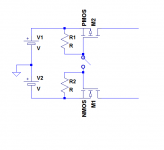
You're thinking of something like this?
I guess that'll work as well, it's cheaper too...
An externally hosted image should be here but it was not working when we last tested it.
Yes, like that. It would be a good idea to have a high value resistor from E-B on each to stop the bases floating when off.
With batteries current consumption is everything so the FET's are perhaps a better solution as the there is no gate current an resistors can be in the meg ohm range.
All depends. If the circuit draws say 10ma then another few tenths of a millamp make no real difference. If the circuit draws 10ua then it's a different story and the switch is drawing much more than the circuit it powers.
Bjts can be good in this configuration when low drop out is needed as the batteries discharge if you get the device choices right.
It shouldn't.It works in simulation.
An externally hosted image should be here but it was not working when we last tested it.
Here is the correct way:
Attachments
It shouldn't.
Here is the correct way:
Hm... funny how it worked in simulation even though I connected it the wrong way around....
But same concept.
Hey, the thread's back from the dead. I like your design Boris.. simple, clean, and neat.
Elvee, I'm not really sure what you did differently. It seems like you moved the switch, but the circuit's still the same. What did I miss?
BTW, thanks to everyone that contributed to this thread. I actually built the amp with the PSU based on raudio's schematic. Works like a charm!

Elvee, I'm not really sure what you did differently. It seems like you moved the switch, but the circuit's still the same. What did I miss?
BTW, thanks to everyone that contributed to this thread. I actually built the amp with the PSU based on raudio's schematic. Works like a charm!
Hey, the thread's back from the dead. I like your design Boris.. simple, clean, and neat.
Elvee, I'm not really sure what you did differently. It seems like you moved the switch, but the circuit's still the same. What did I miss?
BTW, thanks to everyone that contributed to this thread. I actually built the amp with the PSU based on raudio's schematic. Works like a charm!
View attachment 297409
He Swapped the Source and Drain pin of the PMOS
My design shouldn't be able to work IRL but somehow it did in simulation.
Hmmm..... Seems rather complicated just to switch 2 rails...
Both mine and moody's circuits should work fine.
Does it have other functions?
Last edited:
- Status
- This old topic is closed. If you want to reopen this topic, contact a moderator using the "Report Post" button.
- Home
- Design & Build
- Construction Tips
- Switching dual supply rails with a single switch