Hello,
We are doing an offline, 260W , isolated, voltage mode , full-bridge smps. (Vout = +/-50V/2.6A)
We need a fast transient response, but we know that this will be difficult because of the output LC filter. (68uH and 940uF).
This has a severe 180 degree phase drop at the LC resonant frequency (630Hz).
...this in turn makes feedback compensation very difficult.
However,
If we add a series resistor of 0R27 in series with the output capacitance, then the ESR zero frequency becomes 627 Hz.
........Thus we avoid the severe 180 degree phase shift of the output, and turn the power stage into a flyback type stage, which means a faster transient response is much easier to get. (Because there is less delay going through the power stage)
Do you think this is correct?
(The resistor will dissipate 0.6W at max load but this power supply is for audio guitar amplifier and not often at max load.)
Hello,
We are doing an offline, 260W , isolated, voltage mode , full-bridge smps. (Vout = +/-50V/2.6A)
We need a fast transient response, but we know that this will be difficult because of the output LC filter. (68uH and 940uF).
This has a severe 180 degree phase drop at the LC resonant frequency (630Hz).
...this in turn makes feedback compensation very difficult.
However,
If we add a series resistor of 0R27 in series with the output capacitance, then the ESR zero frequency becomes 627 Hz.
........Thus we avoid the severe 180 degree phase shift of the output, and turn the power stage into a flyback type stage, which means a faster transient response is much easier to get. (Because there is less delay going through the power stage)
Do you think this is correct?
(The resistor will dissipate 0.6W at max load but this power supply is for audio guitar amplifier and not often at max load.)
No, because your 940uF capacitor did not start with zero ESR...
i agree, but surely the main thing is that the 180 degree phase shift has been reduced to a maximum 90 degree phase shift....meaning less delay going through the power stage, and ease in getting a fast transient response.
i will just add enough resitance so the esr is always above a certain value
i will just add enough resitance so the esr is always above a certain value
..i cannot use current mode because:
The Input voltage is from around 180V to 375V due to universal mains input...(there is a voltage doubler link)
...this Vin range means current mode is impractical.....so much slope compensation is needed that your virtually in voltage mode anyway, and the primary overcurrent limit is not as tight when you have slope compensation.
so i need voltage mode
Also, voltage mode is less noisy in lighter load conditions
its not pure current mode though.
When you have slope compensation, you are in a combination of voltage mode and current mode.
When you have slope compensation, you have to make the current sense resistor smaller because you have to make room for the added slope ramp.
...so your short circuit protection is not as good as it would be with pure current mode control.
Also, with Bridge converters with dual outputs, you get better cross regulation with voltage mode than you do with current mode.
If you use current mode, you usually have to couple the output inductors.....you dont have to with voltage mode.
Duh, I didn't notice that you had dual outputs. This does change thing a bit, however, I would still go with coupled inductors and current mode control.
I agree with most of what you said, but I'm not aware of what you said about voltage mode cross regulation being better, or why coupled inductors are only needed for current mode. Could you explain that, just for my information.
Finally, if you use a type 3 regulator with voltage mode control, you should be able to improve the performance without adding the resistor to get the zero. The resistor will also increase the output ripple voltage.
http://www.ti.com/lit/an/slua119/slua119.pdf
...current mode vs voltage mode.
As Basso states in his book, when you are using TL431/Opto feedback, the type 3 compensation can often not be achieved.
I would stick to voltage mode, and put the series resistor in to artificially increase esr.
I am sure you would agree that getting rid of the 180 degree sudden phase change is a welcome situation to be in.
And im sure all would agree that slope compensated current mode designs have degraded short circuit protection since the sense resistor has to be downsized to make room for the slope ramp.
This has a severe 180 degree phase drop at the LC resonant frequency (630Hz).
...this in turn makes feedback compensation very difficult.
Not if you can set your crossover frequency sufficiently above the ESR zero. And the prerequisite for that is that the switching frequency is sufficiently above the ESR zero.
Then your compensator only needs to be an integrator + pole/zero pair (or integrator + zero) as shown in the attached diagram.
Attachments
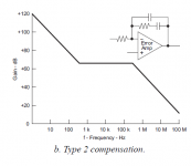
though as you know, the Type 2 compensator only offers up to 90 degree phase boost.
...That just is not enough to handle a Full-Bridge power stage, due to the 180 degree phase lag going through the output LC filter
...the only way Type 2 could work is if you have the crossover frequency way below the output LC resonant frequency.......but then your transient response is terribly slow.
...OR, as i state in the top post, you CAN use a type 2 compensator if you add enough resistance in series with the output caps such that your ESR zero coincides with the output LC filter resonance frequency.
The 180 degree phase lag of the output filter reverts back to 90 degrees above the ESR zero.
Therefore, it is possible to use it, either if you put your crossover frequency below the LC resonance (awfully slow) or above the ESR zero (fast).
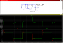
Attached is an example with a 10 kHz crossover frequency.
Therefore, it is possible to use it, either if you put your crossover frequency below the LC resonance (awfully slow) or above the ESR zero (fast).
Attached is an example with a 10 kHz crossover frequency.
Attachments
Last edited:
megajocke:
I believe you are thinking of a current mode ,full-bridge converter.
The one i speak of here is voltage-mode.
In the compensator for voltage mode full-bridge smps, you need two zeros to counteract the double filter pole.
You then need a pole to counteract the ESR zero.
You then need a high freqeuncy pole to make sure the phase and gain margins are ok.
....you simply dont have enough poles and zeros available with a type 2 compensator to achieve the above with a voltage mode, full-bridge* SMPS.
Anyone* who tries to compensate a voltage mode , full-bridge SMPS with a type 2 compensator will be trying unsucessfully for a very very long time.
luka:
The original post points out that if you add series resistance to the output caps, so as to artificially increase the ESR......you can get the ESR zero to be at the same frequency as the output double filter pole......
...IF you do this, THEN you CAN use a Type 2 compensator with a voltage mode full-bridge smps......but not otherwise
No, I'm referring to voltage mode buck/forward/push-pull/bridge/whatever. See the attachment of the last post. It is an average model of a forward family converter with type II compensation and a crossover frequency of 10 kHz. If the switching frequency is sufficiently above the ESR zero it certainly is possible to use type II compensation!
There is no reason why the ESR zero would have to be at the *same* frequency as the double pole of the LC filter.
There is no reason why the ESR zero would have to be at the *same* frequency as the double pole of the LC filter.
OK this is very interesting now,
However, i have not been specific enough in my original post as i realise that i should have pointed out that the chosen method of feedback is TL431/Opto.
....and due to the opto-coupler pole, it simply isn't possible to get cross-over frequencies in the 10KHz ballpark.
So, i apologise for appearing to move the goalposts....but then again, TL431/Opto is the cheapest and most common way of getting isolated feedback.
So can we agree that whilst your Type 2 compensator with high crossover frequency might work for a non-opto-isolated design, Type 3 is needed for designs using TL431/Opto.?
Also, do you appreciate that Type 2 can give maximum 90 degrees phase boost from the -270 degree starting point.
....since the double filter pole gives a 180 degree dip in gain, your type 2 system bode plot will feature a region below the crossover frequency , where the phase plot comes within a few degree of the 360 dgree line?
In other words, your Type 2 solution will have a very low "excess phase" (as per pg205 of Marty Brown's book).
I personally doubt that Type 2, as you descride it, would be capable of giving the right amount of gain that would be needed to lift the control-to-output plot up sufficiently in order to make crossover occur at your wanted high frequency.
....remember also, that the op-amp has its own bandwidth restriction, especially the slow op-amp in a TL431, -so this adds more difficulties for your proposed high bandwidth, Type 2 solution.
Also, your recomendation of type 2 compensator for voltage mode full bridge, is a direct violation of the words of page 216 of the Book "Power supply cookbook", by Marty Brown......Brown is one of the worlds leading smps experts , and writes application notes on smps for Onsemi.com.......one of the biggest smps chip makers in the world.
On page 297 of Basso's book "switch mode power supplies", Basso even states that a Type 3 solution involving TL431/Opto sometimes leads to an impossible solution for V Mode full bridge...........so things look impossible for a type 2 compensator.
I can only imagine that you are referring to a Voltage mode , full bridge converter which is in DCM when you offer a type 2 solution.?
Also, if you are saying that a Type 2 compensator can be used for a voltage mode, Full-Bridge in CCM, then where are you going to place the Type 2 compensator's pole and zero........?
.........you need to be able to answer this specifically, if you cannot answer this then clearly you are not speaking from genuine wisdom about this.
...so , for the Type 2 compensator, would you place the zero at the output double filter pole and the pole at the capacitor esr zero frequency?
....if you would do this, then you would not have enough gain available to you to lift the control-to-output plot up enough to get your required crossover frequency.
You have also described using a relatively high crossover frequency with the type 2 solution, but if crossover frequencies are too high, then the smps becomes susceptible to noise.
Also, why would the Type 3 compensator have been invented if the Type 2 was sufficient?
And why does Christophe Basso not recomend doing Type 2 compensation for a voltage mode, Full-bridge in CCM? (in his book )
Basso, is probably the leading SMPS control expert in the world today.
In short, i would say that Type 2 compensation for Voltage mode, Full-Bridge smps in CCM doesn't work................or at the very least, is a bad idea.
Yeah, with an extra pole from an optocoupler you'll be in trouble and will probably have to do something - either using compensation with a double lead network ("Type III"), removing the pole at the origin (PD-controller with HF gain limit), putting the crossover frequency below the LC resonance, moving the ESR zero to a lower freqency, etc.
As to where to put the "Type II" pole and zero in a CCM forward family voltage mode converter, see this document, for example:
http://www.intersil.com/data/tb/tb417.pdf
That is: pole some distance below LC resonance, zero at high frequency, above crossover. Crossover will be above the ESR zero.
If using capacitors with a high ESR zero frequency (for example ceramics or plastic capacitors) type III compensation will be needed even in optocoupler-free cases because it is not possible to have a crossover frequency higher than the ESR zero. That is also true if the switching frequency is low compared to the ESR zero frequency, which is exactly the same thing really.
Last edited:
Thanks for the article.
...yes i can see that in the most part, we agree with each other....it was my fault for forgetting to initially specify that i am using TL431/Opto feedback.
...we both agree that if the ESR of L and C is not too small, we can get away with type 2 compensation as long as we are not using TL431/Opto feedback
(...for voltage mode , full-bridge types in ccm)
But as you see from my first post, i am actually taking OUR argument a little further.....
I am saying that in Voltage-Mode Full-bridge converter in CCM, -and with TL431/opto feedabck....
....we can improve stability, and more easily get higher loop bandwidth, if we artificially increase the output capacitor ESR by adding a resistor in series with the output caps...........
.....if we add enough resistance such that the output capacitor ESR zero goes to the same frequency as the output double filter pole....then we avoid the 180 degree phase change, and can more easily compensate and achieve faster transient response....without going unstable
..Even Basso, in his book, admits that TL431/Opto feedback in Type 3 cannot always work for Voltage-mode, full-bridge in ccm.
So, for the sake of adding this little cheap resistance , we can make our lives easier...and get a nice fast transient response, which is wanted for supply of Class D amplifiers for electric guitars.
So, has any reader already tried this?
-or can think of any reason why it would not work?
Seriously, with Voltage Mode full bridge converters in ccm with TL431/opto feedback, it is hell on earth to get enough gain and phase margin at a reasonably high crossover frequency ...even with type 3.........
-this is why i recomend the option to artificailly increase the output capacitor ESR.
Does anybody know if this has any disastrously bad scenarios....i cant think of any.
Sure, it should work fine as long as you can live with the increased output ripple. I've never seen this solution used however, probably for that reason. It could also increase effective ESL significantly depending on the resistor type which means more HF and VHF noise on the output.
It is probably a better idea to use the opamp which exists in most PWM controllers to get an extra pole-zero pair in the primary-side circuit, instead of just using the optocoupler current directly to control the duty cycle.
It is probably a better idea to use the opamp which exists in most PWM controllers to get an extra pole-zero pair in the primary-side circuit, instead of just using the optocoupler current directly to control the duty cycle.
- Status
- This old topic is closed. If you want to reopen this topic, contact a moderator using the "Report Post" button.
- Home
- Amplifiers
- Power Supplies
- Improving stability and transient response?