Tone controls are the bane of true audiophiles, or so they say. And if truth be told, there's some real justification for that sentiment. Most traditional tone controls are based on the Baxandall circuit, which in my opinion leaves much to be desired as far as sound quality goes. I've never heard an implementation of that type of tone control that didn't seem to muck up the sound in some way that made things worse. And considering the way the phase and frequency response are treated, and with the inter-channel variation caused by crappy-cheap potentiometers performing thier special kind of "magic", it's no wonder most prefere no tone controls at all.
But inspite of all that, I've always felt the need to have some way of correcting the response aberrations that are almost inevitable given the fact that the recording artist and/or engineer has no way of knowing what the environment that the recording is being played back in will be like. So I've put together a circuit that I believe is functional and good sounding while avoiding the pifalls and shortcomings of the usual designs.
First, the range of adjustment is limited to +/- 7.5dB using 1.5dB switched steps, I can't think of any reason why anyone would need the 15 to 20 dB boost or cut that most controls provide. Using rotary switches instead of pots also avoids the inter-channel variation thing, and allows using a center position to ground to completely disable the tone control action when it's not needed.
Second, instead of the usual 1kHz center point, I've put this one around the mid-600Hz range, which is actually the middle of the audible range of the Human ear.
Third, the slopes are shallower, which makes the adjustments much more subtle but still effective, and also causes less phase shift. There's also a provision for adjusting the turnover frequencies if desired. The final result is a tone control that is usable and won't cause more problems than it solves.
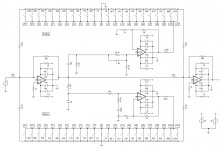
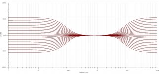
Below are the frequency response plots, schematic and bill of materials.


View attachment Tone Control BOM.txt
Mike
But inspite of all that, I've always felt the need to have some way of correcting the response aberrations that are almost inevitable given the fact that the recording artist and/or engineer has no way of knowing what the environment that the recording is being played back in will be like. So I've put together a circuit that I believe is functional and good sounding while avoiding the pifalls and shortcomings of the usual designs.
First, the range of adjustment is limited to +/- 7.5dB using 1.5dB switched steps, I can't think of any reason why anyone would need the 15 to 20 dB boost or cut that most controls provide. Using rotary switches instead of pots also avoids the inter-channel variation thing, and allows using a center position to ground to completely disable the tone control action when it's not needed.
Second, instead of the usual 1kHz center point, I've put this one around the mid-600Hz range, which is actually the middle of the audible range of the Human ear.
Third, the slopes are shallower, which makes the adjustments much more subtle but still effective, and also causes less phase shift. There's also a provision for adjusting the turnover frequencies if desired. The final result is a tone control that is usable and won't cause more problems than it solves.
Below are the frequency response plots, schematic and bill of materials.
View attachment Tone Control BOM.txt
Mike
Yeah, that's a big problem with the tone controls in many systems. In addition to the built in trimmer adjustment, it's also easy to replace just one cap in the filters to change the range of adjustment if desired.
Woops, I just noticed that I put R1 on the wrong side of C1. Oh well, can't be perfect all the time.")
Mike
Woops, I just noticed that I put R1 on the wrong side of C1. Oh well, can't be perfect all the time.
Mike
Last edited:
Hi Jerryo,
A PCB is certainly more professional looking, but there isn't any reason building it on perfboard would be a problem if one were so inclined. The circuit uses very modest gain levels and is inherently stable, so as long as good layout and construction techniques are used, it's all good. Probably the hardest part of building this is soldering the resistors to the rotary switches, everything else is pretty straight forward and relativly easy. Also, the 1k resistors shown on the non-inverting inputs to ground on the input and output summing amps are there for current limiting bi-polar input OpAmps like the LM4562 to minimize turn-on thumps, they aren't really necessary for FET OpAmps like the OPA2132 shown.
Mike
I have found instability problems with tone controls especially the treble starting to feedback and oscillate.
With all those steps it might be worth looking at a digital pot with 128 or 256 steps.
A push button for up and down could change the pot value.
I am currently working on a USB controlled mixer that drives digital pots. The next step is a tone control using a digital pot.
With all those steps it might be worth looking at a digital pot with 128 or 256 steps.
A push button for up and down could change the pot value.
I am currently working on a USB controlled mixer that drives digital pots. The next step is a tone control using a digital pot.
No instability with this one. With the minimal gain of this design, oscillation is unlikely. Also, my goal was to build something simple and functional that would sound just as good using it as not. I achieved my goal.
Mike
Looks pretty nice but is the step size a little coarse?
G²
Stratus46, the main reason I went with 1.5 dB steps was because I found that it seemed like the best compromise with the shallow slope filters. No reason one couldn't use more steps if desired.
Bcmbob, LDRs would certainly work, but you would lose the center position defeat feature, I suppose you could add a defeat swich if you wanted to go that way. But one of my goals was simplicity and ease of construction. Rotary switches work well here and are simple to use.
Mike
Bcmbob, LDRs would certainly work, but you would lose the center position defeat feature, I suppose you could add a defeat swich if you wanted to go that way. But one of my goals was simplicity and ease of construction. Rotary switches work well here and are simple to use.
Mike
OK, here we go... I built this several years ago, and I'm writing about it from memory, but it's all good, nothing at all difficult about building one. I put the dual OpAmps and surrounding circuitry consisting of the power supply decoupling components, the main signal path resistors and the first order high-pass and low-pass filters on two small PCBs, one for each channel. The two switches are single pole, eleven position, make before break (to prevent switching noises), dual deck rotary type with the cut/boost resistors mounted directly on the terminals. When I built the first prototype I just used a bunch of cheap slide switches I had on hand in place of the rotary switches for testing purposes. Not much else to tell really, like I said before, it's a pretty simple circuit and a relativly easy build. Just use good circuit layout and construction techniques, and decent quality components and you'll end up with a good sounding, usable tone control.
Mike
Mike
In case anyone wants to check it out, here's the zipped TI-Tina spice simulation file.
View attachment Tone Control.zip
TI-Tina is a free SPICE-based analog circuit design and simulation program that can be downloaded here:
TINA-TI License Agreement
Mike
View attachment Tone Control.zip
TI-Tina is a free SPICE-based analog circuit design and simulation program that can be downloaded here:
TINA-TI License Agreement
Mike
Your wish is my command!
I've done some tweeking to the circuit since my last post. It now has a cut / boost range of 11dB in 1dB steps. But what's even better in the new and improved version is that it now has accelerated slope filters based on the work of Dennis Bohn at Rane Corp (Here: http://rane.com/pdf/acceler.pdf.) That type of filter will allow bass and treble adjustment while leaving the mid-band untouched, and it also produces very little phase shift while doing it's thing. Attached below are the schematic, frequency response curves, and a working model in a zipped TI Tina file.
Have fun!
Mike
Attachments
Michael, that looks a very useful circuit!
Your timing is perfect too; I've just come here looking for a way to add an automatic loudness control to the preamp I am designing. I listen at low volume most of the time due to marriage.
Long story short: My 25yo Technics amp is beyond recovery, I'm a digital guy mostly and I'm trying to build a replacement amplifier using parts in my spares boxes if possible (I've no money, due to marriage!). Despite the amp's humble beginnings, I'm now thinking of using a microcontroller to control it all digitally.
Looking at your circuit, I think that I could replace the boost side of the base and treble sections with two 20KΩ digital potentiometers, with the wipers paralleled to ground with 5KΩ resistors. Since I only need to boost for a loudness control, the other side of the resistor chains could be replaced with a 4KΩ resistors.
That way, I would have about the same range of adjustment on the boost side as your circuit, with the 10-bit digipot scaled appropriately in software. The idea then is for the MCU to automatically control the amount of boost based on the volume level.
Do you think this is a reasonable idea?
- Home
- Amplifiers
- Chip Amps
- A usable tone control