To reduce the four than before to 2. But it is more low price and easy installation.
And NJW0302G power is bigger, overall output power 200 W 8 R (+ 65 V)
Would not reduce the output power.
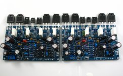
Please note that blue PCB genuine original,
Designers LJM.
I will name L20SE life for it, to distinguish them from.

And NJW0302G power is bigger, overall output power 200 W 8 R (+ 65 V)
Would not reduce the output power.
Please note that blue PCB genuine original,
Designers LJM.
I will name L20SE life for it, to distinguish them from.
Attachments
Two pair of plastic packaged To247 or To3p will be highly stressed driving an 8ohm speaker from +-65Vdc supply rails.
Two pair of metal packaged, high temperature, high power To3 will cope with this if you can keep them warm but not hot.
Reducing to one pair on +-65V supply rails is virtually guaranteeing early failure, even into 8ohms. Into 16ohm, low to medium reactance speakers, one pair might survive to a long life.
Two pair of plastic packaged To247 or To3p will be highly stressed driving an 8ohm speaker from +-65Vdc supply rails.
Two pair of metal packaged, high temperature, high power To3 will cope with this if you can keep them warm but not hot.
Reducing to one pair on +-65V supply rails is virtually guaranteeing early failure, even into 8ohms. Into 16ohm, low to medium reactance speakers, one pair might survive to a long life.
CLASS AB Efficiency about 65%.
OUTPUT 200W POWER,Loss power about 35%. 107 watt.
They will share in these transistors TO-3P。NJW0302G+ NJW0281G
the 107W is an average power prediction for driving an 8r0 resistor load.CLASS AB Efficiency about 65%.
OUTPUT 200W POWER,Loss power about 35%. 107 watt.
They will share in these transistors TO-3P。NJW0302G+ NJW0281G
This 107W cannot be used to determine whether the transistors will survive driving an 8ohm speaker when the devices start to warm up or worse get hot.
I will give you free starter:
A two pair output stage driving 200W into an 8r0 resistor, will get warm. Calculate what temperature the device cases (Tc) will be for your average power dissipation in each device.
From the Tc that you determined, calculate the Pmax that the devices can dissipate.
Is this average dissipation more or less than the DC (continuous) power rating for the device operating at that Tc?
Is this average more or less than the 100ms one shot power rating for the device operating at that Tc?
Is this average more or less than the 10ms one shot power rating for the device operating at that Tc?
Is this average more or less than the 1ms one shot power rating for the device operating at that Tc?
Is this average more or less than the 100us one shot power rating for the device operating at that Tc?
Now that you are into short term one shot transients, you must consider not the average dissipated power but the instantaneous peak dissipated power.
Next stage is to repeat those comparisons using resistor loading and instantaneous Pmax, to all those temperature de-rated SOA limits.
Finally, the difficult bit, you need to examine what effect changing from a resistive load to a reactive load does to the average P and instantaneous Pmax and use this information to make all those comparisons again.
Manually this is a lot of work.
David Eather shows a manual method for doing this.
Benson gives a spreadsheet to convert the manual method to computer assisted for mosFET output stage.
There are other computer assisted methods available to Members.
Start with Eather so that you can understand what it is that you need to know to make the assessment that you originally asked for.
Last edited:
With 65 volt supply and 8 ohms, worst case power in the output devices is around 132 watts, which occurs at less than full power out. I agree that 107 watts is around the power in the output devices at full power out. Heatsinks need to be designed for WORST CASE power dissipation, IMHO. One pair of devices will be highly stressed, like AndrewT said. More output devices tend to makes things better as long as the heatsink is big enough.
the 107W is an average power prediction for driving an 8r0 resistor load.
This 107W cannot be used to determine whether the transistors will survive driving an 8ohm speaker when the devices start to warm up or worse get hot.
I will give you free starter:
A two pair output stage driving 200W into an 8r0 resistor, will get warm. Calculate what temperature the device cases (Tc) will be for your average power dissipation in each device.
From the Tc that you determined, calculate the Pmax that the devices can dissipate.
Is this average dissipation more or less than the DC (continuous) power rating for the device operating at that Tc?
Is this average more or less than the 100ms one shot power rating for the device operating at that Tc?
Is this average more or less than the 10ms one shot power rating for the device operating at that Tc?
Is this average more or less than the 1ms one shot power rating for the device operating at that Tc?
Is this average more or less than the 100us one shot power rating for the device operating at that Tc?
Now that you are into short term one shot transients, you must consider not the average dissipated power but the instantaneous peak dissipated power.
Next stage is to repeat those comparisons using resistor loading and instantaneous Pmax, to all those temperature de-rated SOA limits.
Finally, the difficult bit, you need to examine what effect changing from a resistive load to a reactive load does to the average P and instantaneous Pmax and use this information to make all those comparisons again.
Manually this is a lot of work.
David Eather shows a manual method for doing this.
Benson gives a spreadsheet to convert the manual method to computer assisted for mosFET output stage.
There are other computer assisted methods available to Members.
Start with Eather so that you can understand what it is that you need to know to make the assessment that you originally asked for.
Welcome your comments.
L20 can be installed transistors to 4。
OR 2 。
OUTPUT + -60V. 6.6 OHM
use a small aluminum。yes, it's very hot. I added a small fan. Not hot.
Attachments
Last edited:
The minimum configuration I have checked was 2 pairs of NJW0xxx, with +/-63V. It was OK, even with 4ohm resistive load, but the distortion was increased by 20dB with 4ohm load compared to 8ohm load.
And it needs very heavy protection, and sometimes shut down itself with 4ohm reactive load.
Sajti
And it needs very heavy protection, and sometimes shut down itself with 4ohm reactive load.
Sajti
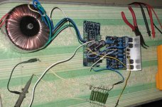
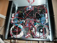
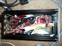
i use both L20 and L20SE.
power output in real life situations is the same.
i use 4 ohm transmissionline speakers.
on the picture you see the speaker protect kit "unactive". I have ordered a new power supply. the ones i bought did ........MELT!
Sound is great.
don forget to change the 10uf into ....silmic 2 or nichicom muze versions....upto what you like!!!
sounds less metallic and more natural. differences easy to hear with classical music..violin etc...
i use in my preamp 2x jantzen superior z-cap + PGA2310
Best regards,
- Home
- Amplifiers
- Solid State
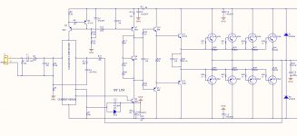
- L20 AMP。use only two NJW0302G