Hi,
I have been thinking about super regulating the +/- 70 V of the BOSOZ or some type of X variation thereof...would that be worth it? I have quite a few BB 3584JM high voltage opamp to use in place of the AD825.
The voltage seems to be in an intermediate range that is too high for the std superreg but maybe too low for shunt reg, I don't know.
Anythink wrong with the idea? Or would it be better to redesign the BOSOZ for lower voltage around a small signal mosfet like ones in the ZETEX series?
Well, whether or not it's worth it for your application I'm not sure (I don't know what a BOSOZ is). But I've been playing around with sims for a design of a super reg of +/- 90 V at about 100 mA (with 300 mA transients or so) for a class B MOSFET power amp minus the output stage. It's not necessary to use a high-voltage op-amp. The design I have uses a TL431 as a shunt regulator of 30 V for a normal op-amp, with the shunt regulator bias resistor bootstrapped to the 90 V regulated output. One drawback is the bias resistor dissipates about one Watt. I chose the 8-pin DIP version of the TL431 instead of the TO-92 for thermal reasons, as it dissipates about 300 mW. Just choose the zener diode in the output stage so that the op-amp output is biased midway between its rails, about 15V. I use zeners that total about 75 Volts here.
BOSOZ = Nelson Pass balanced linestage or bride of son of zen.
What I was thinking was to use the ALW/Jung circuit. In the standard circuit the superreg op amp is an AD 825 which is fed by the super regulated output voltage (up to 30V output) the LM317 is already present and functions as a pre regulator.
I looked at the datasheet of the 3485JM again and the PS voltage needed is too high! I guess I misread the oprating voltage. A minimum of 70-0-70 to a max of 150-0-150. At 300 V it looks like I could make a Jung super reg for a tube amp!
Hi Grataku,
I've been playing with this a long time ago, and even mailed Walt Jung to have some hints about the HV problem, and he replied quite gently. Normaly, everything should work fine, except that you will have to address a huge dissipation issue, both in the op-amp and in the controlled BJT. I used an OPA445 from BB (now TI), rated for 90V in a 80V supply, and it ran quite hot . The only way - AFAIK - to reduce the dissipation is to lower the current delivered by the op-amp to the base of the BJT. So it requires some trimming, adjusting the CCS current and chosing a high gain BJT. Such power BJTs are not common (high gain doesn't suit to power requirements). I ended up with a power darlington. I had no sufficient Vout-Vin drop in my app to use a power mosfet as pass element, but I still wonder if a Mosfet would give the same overall performances than a BJT...
Just my ...
...
I've been playing with this a long time ago, and even mailed Walt Jung to have some hints about the HV problem, and he replied quite gently. Normaly, everything should work fine, except that you will have to address a huge dissipation issue, both in the op-amp and in the controlled BJT. I used an OPA445 from BB (now TI), rated for 90V in a 80V supply, and it ran quite hot
. The only way - AFAIK - to reduce the dissipation is to lower the current delivered by the op-amp to the base of the BJT. So it requires some trimming, adjusting the CCS current and chosing a high gain BJT. Such power BJTs are not common (high gain doesn't suit to power requirements). I ended up with a power darlington. I had no sufficient Vout-Vin drop in my app to use a power mosfet as pass element, but I still wonder if a Mosfet would give the same overall performances than a BJT...Just my
...peranders said:Have you thought about the simple LM317? This regulator can regulate rather high voltage if not the voltage across it isn't more than 35 (60) volts. One thing to remember: The feedback network consumes power, rather much, at high voltages.
With the LM317, how does one solve the problem of having the entire unregulated input voltage appearing across the internal pass element at startup without having a large voltage drop in series with the unregulated input in normal operation?
use the TL783
this is a 125 volt regulator from Texas Instruments -- just outboard a heftier pass transistor.
you can then go the further mile by using the Wenzel Associates feedback design to get the noise down further -- to that approaching a low noise reference. Seems like a lot of work for a power amp, but that's what we're in business for.
don't forget also that you can always regulate the ground return leg of a single ended power supply.
andy_c said:
With the LM317, how does one solve the problem of having the entire unregulated input voltage appearing across the internal pass element at startup without having a large voltage drop in series with the unregulated input in normal operation?
The standard cheating way of using a zener from adjust to ground. The reg tries to maintain the 1.25 V across the resistor from output to adjust so when you put e.g. a 75 zener from adjust to ground then you can handle some 125 V input and regulate between 76.25 and some 120 V.
UrSv said:
The standard cheating way of using a zener from adjust to ground. The reg tries to maintain the 1.25 V across the resistor from output to adjust so when you put e.g. a 75 zener from adjust to ground then you can handle some 125 V input and regulate between 76.25 and some 120 V.
The problem I'm referring to is at startup. At this time, the regulated output voltage is zero because the output cap hasn't begun charging up, and the unregulated input is, say, 100 Volts for a 90 Volt regulator. So there's 100 V across the pass element in this condition. Putting a zener from adjust to ground does not affect the differential between the unregulated input and the regulated output in this case.
The disadvantage of using a 317 floating at high voltage is that you need a high division ratio in the feedback to set the output. The regulation factor and basically all performance numbers including noise deteriorate with that division factor. The 783 has the same problem (if you want to call it that).
It is something to keep in mind when making a choice between a floating 317 with reduced performance, or a regulator based on a high voltage opamp, which will lose some performance because of the not-so-hot opamp.
Jan Didden
It is something to keep in mind when making a choice between a floating 317 with reduced performance, or a regulator based on a high voltage opamp, which will lose some performance because of the not-so-hot opamp.
Jan Didden
Re: this will work - regulating the ground
The question shouldn't be whether it works, as many designs do, but whether they fulfill what Jung's regulator was after: low noise and low impedance.
The critical comments over Sulzer's or Jung's regulators were that they used massive feedback to lower impedance, and it was claimed that affected the audio quality in a bad way. Shunt designs are said to be better in that area, but I haven't found many people that compared them and were not biased in some way to provide a satisfactory answer as to which sounded better or how the audio quality was affected.
The next question on Jung style high voltage regulators is if they can be used as high current ones, to regulate power amps.
Carlos
jackinnj said:this design is in The Art of Electronics and it really works:
The question shouldn't be whether it works, as many designs do, but whether they fulfill what Jung's regulator was after: low noise and low impedance.
The critical comments over Sulzer's or Jung's regulators were that they used massive feedback to lower impedance, and it was claimed that affected the audio quality in a bad way. Shunt designs are said to be better in that area, but I haven't found many people that compared them and were not biased in some way to provide a satisfactory answer as to which sounded better or how the audio quality was affected.
The next question on Jung style high voltage regulators is if they can be used as high current ones, to regulate power amps.
Carlos
Re: this will work - regulating the ground
Err... What is so special about this one? Just a clever way of redrawing and taking the ref point from another circuit node. It's a standard feedback regulator. And we know these work.
Jan Didden
jackinnj said:this design is in The Art of Electronics and it really works:
Err... What is so special about this one? Just a clever way of redrawing and taking the ref point from another circuit node. It's a standard feedback regulator. And we know these work.
Jan Didden
Re: Re: this will work - regulating the ground
You can use a cheaper transistor.
janneman said:
Err... What is so special about this one? Just a clever way of redrawing and taking the ref point from another circuit node. It's a standard feedback regulator. And we know these work.
Jan Didden
You can use a cheaper transistor.
Re: Re: this will work - regulating the ground
If you're talking about regulating the supply voltage of the output stage, that's a tall order for any regulator. I'd consider that a "radical design".
But there are other cases where a regulated supply for a power amp is not a radical design at all. Consider a MOSFET power amp. The drivers don't need to supply much current to the gates of the MOSFETs at all under steady-state conditions. So you can use a regulator for everything but the output stage. This is also an advantage for a MOSFET design as you can increase the supply voltage to the circuitry driving the output stage to make up for the loss of voltage swing incurred in the MOSFET design from the high Vgs.
But how much current is supplied to the gates of the MOSFETS under worst-case transient conditions? I've simulated the equivalent of the Holton AV-800 output stage with seven each IRFP240/IRFP9240 in parallel, driven by IRF610/IRF9610 MOSFET drivers. In driving a square wave at 20 kHz with the same peak value as a sine wave representing 300 Watts into 8 Ohms, the drivers put out pulses of gate current to the output stage peaking out at about 300 mA with rise and fall times of around 500 ns.
So in simulating my regulator design, I use an ideal controlled source plus an R and C to get pulses of load current with the required rise and fall times, and look at the transient response of the output voltage. My other main performance criterion is ripple rejection of the line voltage at 120 Hz.
But what about the supply voltage rejection of the power amp output stage compared to the rest of the amp? I've found through simulation that the supply rejection of "everything else" for a complementary amplifier design is approximately equal to the loop gain, indicating an open-loop supply rejection of close to 0 dB (consistent with theory BTW). In simulating the supply rejection of the output stage, the Holton AV-800 output stage has 95 dB of ripple rejection at 120 Hz, degrading to about 50 dB at 20 kHz. So the part of the amp with the worst supply rejection is the low-current part.
So it sure looks like using a regulator for everything but the output stage of a MOSFET power amp is a good compromise. Increased output swing, improved ripple rejection, and most likely reduced distortion are all big benefits.
The Jung-style "super reg" can be used without very many modifications. As I mentioned earlier, the TL431 can be used as a 30 Volt shunt regulator for the op-amp, supplied from a series resistor connected to the regulated output (in my case, 90 Volts). This allows conventional op-amps to be used. The zener diode voltages in the output stage should be set so the op-amp output is biased to about 15 Volts, halfway between the rails. The zener voltages end up totaling about 75 Volts to do this for a 90 Volt regulator. Since the base current of the pass transistor becomes non-negligible for the worst-case load I'm looking at (and the relatively low beta of the high-voltage pass transistors), I ended up using two transistors in a Darlington configuration as the pass element. Also, it appears that a pre-reg isn't practical here, as the pre-reg could see the full unregulated input voltage as an input-output differential during startup. This means the ripple rejection should be as large as possible at 120 Hz, since we can't depend on a pre-reg to improve matters here. That brings us to the choice of op-amp, and stability considerations.
I wasn't able to get good transient response simulations with any op-amp when the capacitor was placed in parallel with the feedback resistor. There's just too much loop gain at high frequencies to make this work. I ended up removing the capacitor. For op-amps, I started out trying the 797. It appears that in simulation, the 797 is as problematic with stability as it is in practice. Even with the feedback capacitor removed the 797-based regulator had a nasty ringing on the output with the load current pulse. The regulator had better load current transient response with the 825 than any other op-amp I tried. However, the 825 has its dominant open-loop pole at about 10 kHz. So a similar op-amp with the same gain-bandwidth product, but with a dominant open-loop pole at, say, 10 Hz will have about 40 dB more open-loop gain at 120 Hz than the 825. So it's possible to get 40 dB better ripple rejection at 120 Hz with an op-amp with higher low frequency gain. With that in mind, I ended up experimenting with other op-amps. The best compromise I found was the venerable OP-37. Transient response to the load current pulse was almost as good as with the 825, but the ripple rejection at 120 Hz was almost 40 dB better. So that's what I settled on.
The other key to getting good transient response simulations was having a reasonably accurate model of the parasitic effects of the 100 uF output capacitor. From the Rubycon web site, I found the series resonant frequency of the cap to be around 100 kHz, with a series resistance of about a quarter of an Ohm. It's essential to model this behavior, as it's an integral part of the regulator stability and without it you have an oscillator. At 100 kHz, you get pure attenuation with no phase shift from the resistive output impedance of the pass element and the 0.25 Ohm resistance of the output capacitor at series resonance. I suspect that the reason I had to remove the cap in parallel with the feedback resistor was that the load current of this regulator is much higher than the typical Jung regulator used for preamps. This means the open-loop output resistance of the pass element is lower by the same factor. So there's corrrespondingly less attenuation of the loop gain at 100 kHz from the output capacitor impedance-pass element output impedance combo. So I needed more attenuation of the loop gain, which was accomplished by removing the cap from the feedback loop. One interesting side note is that ALW has stated that the sound of his preamp with the super reg improved when he removed this capacitor. I wonder if this was due to improved transient response due to improved stability. Hmm...
Well, I'd better shut up now, as I somehow got into the "data dump" mode...")
Originally posted by carlmart
(...) The next question on Jung style high voltage regulators is if they can be used as high current ones, to regulate power amps.
If you're talking about regulating the supply voltage of the output stage, that's a tall order for any regulator. I'd consider that a "radical design".
But there are other cases where a regulated supply for a power amp is not a radical design at all. Consider a MOSFET power amp. The drivers don't need to supply much current to the gates of the MOSFETs at all under steady-state conditions. So you can use a regulator for everything but the output stage. This is also an advantage for a MOSFET design as you can increase the supply voltage to the circuitry driving the output stage to make up for the loss of voltage swing incurred in the MOSFET design from the high Vgs.
But how much current is supplied to the gates of the MOSFETS under worst-case transient conditions? I've simulated the equivalent of the Holton AV-800 output stage with seven each IRFP240/IRFP9240 in parallel, driven by IRF610/IRF9610 MOSFET drivers. In driving a square wave at 20 kHz with the same peak value as a sine wave representing 300 Watts into 8 Ohms, the drivers put out pulses of gate current to the output stage peaking out at about 300 mA with rise and fall times of around 500 ns.
So in simulating my regulator design, I use an ideal controlled source plus an R and C to get pulses of load current with the required rise and fall times, and look at the transient response of the output voltage. My other main performance criterion is ripple rejection of the line voltage at 120 Hz.
But what about the supply voltage rejection of the power amp output stage compared to the rest of the amp? I've found through simulation that the supply rejection of "everything else" for a complementary amplifier design is approximately equal to the loop gain, indicating an open-loop supply rejection of close to 0 dB (consistent with theory BTW). In simulating the supply rejection of the output stage, the Holton AV-800 output stage has 95 dB of ripple rejection at 120 Hz, degrading to about 50 dB at 20 kHz. So the part of the amp with the worst supply rejection is the low-current part.
So it sure looks like using a regulator for everything but the output stage of a MOSFET power amp is a good compromise. Increased output swing, improved ripple rejection, and most likely reduced distortion are all big benefits.
The Jung-style "super reg" can be used without very many modifications. As I mentioned earlier, the TL431 can be used as a 30 Volt shunt regulator for the op-amp, supplied from a series resistor connected to the regulated output (in my case, 90 Volts). This allows conventional op-amps to be used. The zener diode voltages in the output stage should be set so the op-amp output is biased to about 15 Volts, halfway between the rails. The zener voltages end up totaling about 75 Volts to do this for a 90 Volt regulator. Since the base current of the pass transistor becomes non-negligible for the worst-case load I'm looking at (and the relatively low beta of the high-voltage pass transistors), I ended up using two transistors in a Darlington configuration as the pass element. Also, it appears that a pre-reg isn't practical here, as the pre-reg could see the full unregulated input voltage as an input-output differential during startup. This means the ripple rejection should be as large as possible at 120 Hz, since we can't depend on a pre-reg to improve matters here. That brings us to the choice of op-amp, and stability considerations.
I wasn't able to get good transient response simulations with any op-amp when the capacitor was placed in parallel with the feedback resistor. There's just too much loop gain at high frequencies to make this work. I ended up removing the capacitor. For op-amps, I started out trying the 797. It appears that in simulation, the 797 is as problematic with stability as it is in practice. Even with the feedback capacitor removed the 797-based regulator had a nasty ringing on the output with the load current pulse. The regulator had better load current transient response with the 825 than any other op-amp I tried. However, the 825 has its dominant open-loop pole at about 10 kHz. So a similar op-amp with the same gain-bandwidth product, but with a dominant open-loop pole at, say, 10 Hz will have about 40 dB more open-loop gain at 120 Hz than the 825. So it's possible to get 40 dB better ripple rejection at 120 Hz with an op-amp with higher low frequency gain. With that in mind, I ended up experimenting with other op-amps. The best compromise I found was the venerable OP-37. Transient response to the load current pulse was almost as good as with the 825, but the ripple rejection at 120 Hz was almost 40 dB better. So that's what I settled on.
The other key to getting good transient response simulations was having a reasonably accurate model of the parasitic effects of the 100 uF output capacitor. From the Rubycon web site, I found the series resonant frequency of the cap to be around 100 kHz, with a series resistance of about a quarter of an Ohm. It's essential to model this behavior, as it's an integral part of the regulator stability and without it you have an oscillator. At 100 kHz, you get pure attenuation with no phase shift from the resistive output impedance of the pass element and the 0.25 Ohm resistance of the output capacitor at series resonance. I suspect that the reason I had to remove the cap in parallel with the feedback resistor was that the load current of this regulator is much higher than the typical Jung regulator used for preamps. This means the open-loop output resistance of the pass element is lower by the same factor. So there's corrrespondingly less attenuation of the loop gain at 100 kHz from the output capacitor impedance-pass element output impedance combo. So I needed more attenuation of the loop gain, which was accomplished by removing the cap from the feedback loop. One interesting side note is that ALW has stated that the sound of his preamp with the super reg improved when he removed this capacitor. I wonder if this was due to improved transient response due to improved stability. Hmm...
Well, I'd better shut up now, as I somehow got into the "data dump" mode...
HV Jung Schematic
Hi All
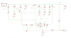
I thought I would resurrect this thread and see what you all thought of this attached schematic of a high voltage Jung regulator and if any potential issues were immediately obvious.
As per Andy's suggestion I used the TL431 to power the error amp so it is always dropping about 30 volts independent of the output voltage ( within limits of course ).
I plan to use this to power a tube line amp that would draw approximately 150mA @ 140 Volts.
I look forward to your suggestions
Hi All
I thought I would resurrect this thread and see what you all thought of this attached schematic of a high voltage Jung regulator and if any potential issues were immediately obvious.
As per Andy's suggestion I used the TL431 to power the error amp so it is always dropping about 30 volts independent of the output voltage ( within limits of course ).
I plan to use this to power a tube line amp that would draw approximately 150mA @ 140 Volts.
I look forward to your suggestions
Attachments
Neat!
I was just looking at your R13. This resistor will need to absorb all the excess current the opamp slurps up, which varies with load currewnt, and do so without getting the 431 lose control. Have you looked at the actual size of it? Is the 20k a design value or a placeholder in the diagram?
jan didden
Quite an accomplishment that HV Jung version!
I imagine that you set the output voltage with R11/R12 and the IC voltage with R9/R10, right?
For the regulator output, if Vref is 6.9v, then R11 should 1K for 144v, me thinks.
My interest is because I'm considering several regulator designs to use on the low-current regulators on my power amps, which now use 3X7 types and I would like to improve on them. But I didn't know how to get to use Jung/Didden regs for my voltages, which would be +/- 60 or 65 volts, or even 70.
Would these regulator design be an "exaggeration" on such application?
Carlos
Quite an accomplishment that HV Jung version!
I imagine that you set the output voltage with R11/R12 and the IC voltage with R9/R10, right?
For the regulator output, if Vref is 6.9v, then R11 should 1K for 144v, me thinks.
My interest is because I'm considering several regulator designs to use on the low-current regulators on my power amps, which now use 3X7 types and I would like to improve on them. But I didn't know how to get to use Jung/Didden regs for my voltages, which would be +/- 60 or 65 volts, or even 70.
Would these regulator design be an "exaggeration" on such application?
Carlos
Carlos,
The original Jung/Didden regs use the reg output as supply for the error amplifier. That limits Vout to whatever the opamp can sustain.
However, if you feed the opamp from a separate integrated regulator, that limitation is removed and there's not theoretical limit to Vout as long as the pass device can handle it (and with an appropriate value zener in series with the opamp output of course).
For instance, there are 3-pin integrated regulators that are perfect to feed an opamp from up to 100V like the TL783 and the LR8, or the LR12 for up to 400V. These only supply a few 10's of mA but that's enough for an opamp.
I've played with those and they work pretty well.
jan didden
- Status
- This old topic is closed. If you want to reopen this topic, contact a moderator using the "Report Post" button.
- Home
- Amplifiers
- Solid State
- Hi voltage Jung super reg