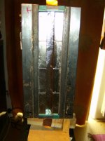
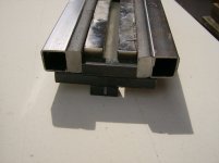
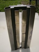
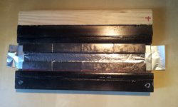
I have built a very simple module that can easely be stacked on top of another to build a long line array. The idea is to use the two steel tubes that will fit on two long steel bars.
The ribbon area is 20 cm x 1.2 cm (or 1.0 cm). The steel frame is 22 cm long.
One of the picture shows a ribbon of 0.8 microns thick (no breathing allowed near the ribbon!). Aluminium foils provider: Foils List.
Magnet: 1.4 x 1.5 x 5 cm , N48.
Magnetic field strength: 0.74 and 0.64 T for the 1 cm gap; 0.70 and 0.58 for the 1.2 cm gap. The smaller value is for the middle of the gap, the larger for the magnet surface. Measurement were performed with a Hirst GM05 gaussmeter.
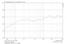
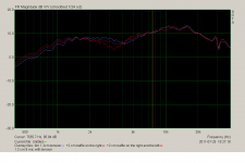
Frerquency response measured at a distance of 52 cm with ARTA.
The ribbon area is 20 cm x 1.2 cm (or 1.0 cm). The steel frame is 22 cm long.
One of the picture shows a ribbon of 0.8 microns thick (no breathing allowed near the ribbon!). Aluminium foils provider: Foils List.
Magnet: 1.4 x 1.5 x 5 cm , N48.
Magnetic field strength: 0.74 and 0.64 T for the 1 cm gap; 0.70 and 0.58 for the 1.2 cm gap. The smaller value is for the middle of the gap, the larger for the magnet surface. Measurement were performed with a Hirst GM05 gaussmeter.
Frerquency response measured at a distance of 52 cm with ARTA.
Attachments
Why not one long run ? disadvantage , advantages with stacking .......
I think the chosen 12mm width is about optimal
magnet field weakens beyond that
and with 12mm a long ribbon becomes hard to handle
mechanical constructing is easier as well
but you get higher Fs with short ribbon
but quite good if it does 1khz
Why not one long run ? disadvantage , advantages with stacking .......
Good question.
Advantages:
- safety: putting together two long rows of magnets is difficult and dangerous because of the strong forces involved
- less weakening of the magnetic field with the increases of the ribbon length
- more choice for the ribbon material (e.g. 2.5 microns, 25 x 25 cm sheet from Lebowfoils)
- I plan to build a straight line and a concave line and compare both
Disadvantages:
- magnetic field in the gap is not as homogenous
- comb filtering could occur if the dead space separating the ribbon radiation areas is too large
Dip at 4 KHz
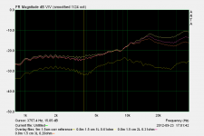
The frequency response of my ribbon modules shows a dip at about 4 to 5 KHz.
I wonder where this dip is coming from?
If I would increase the width of the left and right sides of the ribbon module, by attaching another 2 x 2 cm rectangular tube on each side (see pictures in the first post of this thread), then the frequency of the dip would go lower. The frequency responses are shown in the first picture atached to this post.
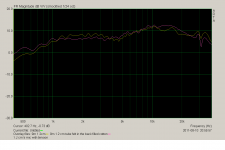
If I cover the back of the driver with felt, then the dip dissapears and the level at 2 KHz is slightly lower (second attached picture).
I first thought this effect was due to the diffraction from the edges. I don't think this is the cause of the dip because when adding felt in the back of the driver, the dip is strongly attenuated.

The frequency response of my ribbon modules shows a dip at about 4 to 5 KHz.
I wonder where this dip is coming from?
If I would increase the width of the left and right sides of the ribbon module, by attaching another 2 x 2 cm rectangular tube on each side (see pictures in the first post of this thread), then the frequency of the dip would go lower. The frequency responses are shown in the first picture atached to this post.
If I cover the back of the driver with felt, then the dip dissapears and the level at 2 KHz is slightly lower (second attached picture).
I first thought this effect was due to the diffraction from the edges. I don't think this is the cause of the dip because when adding felt in the back of the driver, the dip is strongly attenuated.
Attachments
The frequency response of my ribbon modules shows a dip at about 4 to 5 KHz.
I wonder where this dip is coming from?
If I would increase the width of the left and right sides of the ribbon module, by attaching another 2 x 2 cm rectangular tube on each side (see pictures in the first post of this thread), then the frequency of the dip would go lower. The frequency responses are shown in the first picture atached to this post.
If I cover the back of the driver with felt, then the dip dissapears and the level at 2 KHz is slightly lower (second attached picture).
I first thought this effect was due to the diffraction from the edges. I don't think this is the cause of the dip because when adding felt in the back of the driver, the dip is strongly attenuated.
Cavity resonance.
Cavity resonance.
Which cavity do you have in mind? Could you elaborate?
Thanks
Which cavity do you have in mind? Could you elaborate?
Thanks
The ribbon hangs between the two magnet rows, Those magnets are spaced between maybe one and five cm from each other, depending from ribbon.
Then we have the magnet depht, maybe 2- 4cm, depending on magnet size.
Those both values fome a cavity , which make reflections and form the resonance. The structural integrity of the ribbon itself is also not to forget.
Say the space is 3 x 4 cm, the F res will be somewhere around 5-7 Khz and can be easy up to 6 dB.
To lower the effect you can put the ribbon more forward to the front of the magnets and use magnets with less depth and most important, make the edges round to optimize the diffraction and use magnet formed like pole shoes.
Or you can use a tank circuit, but this will cost you efficiency and money for parts.
The ribbon hangs between the two magnet rows, Those magnets are spaced between maybe one and five cm from each other, depending from ribbon.
Then we have the magnet depht, maybe 2- 4cm, depending on magnet size.
Those both values fome a cavity , which make reflections and form the resonance. The structural integrity of the ribbon itself is also not to forget.
Say the space is 3 x 4 cm, the F res will be somewhere around 5-7 Khz and can be easy up to 6 dB.
The two 20 cm long magnet rows are spaced by 1.2 cm.
The magnets are 1.5 cm deep.
Could you predict the frequency of the observed dip (measured at 4 to 5 KHz) ?
To lower the effect you can put the ribbon more forward to the front of the magnets and use magnets with less depth and most important, make the edges round to optimize the diffraction and use magnet formed like pole shoes.
Or you can use a tank circuit, but this will cost you efficiency and money for parts.
When I move the ribbon more forward to the front of the magnets (the ribbon is about 1 -2 mm deep from the top) then the dip increases by 4 - 5 db , but the frequency remains the same. On the other hand, when I move the ribbon more backward, close to the back of the magnets (the ribbon is then about 13 -14 mm deep from the top), then the dip disappears.
Also, when I place the measurement microphone very close to the ribbon (less than a few cm, I don't remember exactly), then the dip disappears (the ribbon was placed in the middle the gap).
Adding wings to the side of the ribbon decreases the frequency of the dip and increases the intensity of the dip.
Decreasing the height of the ribbon, from 20 to 5 cm, does not affect the dip.
Increasing the distance between the two magnet rows (=wider ribbon gap) does not affect the dip (distances tried: 1.0, 1.2 , 1.5 and 2.2 cm).
Bruno
On the other hand, when I move the ribbon more backward, close to the back of the magnets (the ribbon is then about 13 -14 mm deep from the top), then the dip disappears.
Bruno
I use felt behind the ribbon
and its placed in line with front of magnets, with waveguide
Hi Bruno
Sorry, im no expert.
What i wrote is from experience with Apogee Ribbonspeakers and what they wrote in their patent letters, how to reduce those and other effects.
But they had pretty long ribbons, between 60 and 200cm, so the effect is maybe different.
But what is astonishing, the cavity resonance gives usually a broad peak, not a dip.
So maybe i am on the wrong path.
I did not read correct first, what you wrote. Sorry.
My german is better for sure.
Just as an idea:
What happens with a longer ribbon and lesser tension?
Your dip is apx. 4 khz, giving a wavelength around 8cm.
Last edited:
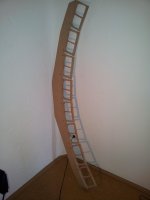
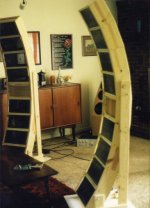
Concave line array in progress
I started building a concave line array that will be made of 8 ribbon units.
Height: about 170 cm. Listening distance : 138 cm. All units will aim at this distance.
I have never seen and heard such a design (if you know one, please post!).
Possible advantages:
- unusual large vertical listening angle => huge image
- unusual large surface for a tweeter: 24 x 8 = 192 cm2
Disavantages:
- only one listener
Each unit will use several layers of 0.8 micron aluminium foil.
XO: 1000 Hz, first order with a planar.
Bruno
Attachments
I started building a concave line array that will be made of 8 ribbon units.
Height: about 170 cm. Listening distance : 138 cm. All units will aim at this distance.
I have never seen and heard such a design (if you know one, please post!).
Bill Waslo(Liberty Instruments) wrote a 3 part article in Speaker Builder magazine back in 1998 on design and construction of a focused-array ESL.
I seem to recall Bill summarized the listening experience as "you are there" rather than "they are here".
Definitely a very large single listener setup.
You might contact bwaslo here on DIYaudio if you want further details on his design and listening impressions of the concave line array.
Attachments
Bill Waslo(Liberty Instruments) wrote a 3 part article in Speaker Builder magazine back in 1998 on design and construction of a focused-array ESL.
I seem to recall Bill summarized the listening experience as "you are there" rather than "they are here".
Definitely a very large single listener setup.
You might contact bwaslo here on DIYaudio if you want further details on his design and listening impressions of the concave line array.
Thanks. I have sent him a PM inviting him to write a post.
Bruno
Thanks. I have sent him a PM inviting him to write a post.
Bruno
very interesting, any news?
I would like very much to see vertical polar plots of such a focused array
Focused array
Bill did answer me but unfortunately, he did not post here. I hope that he will not mind if I post his answer here - IMO this is unique and valuable information that is worth posting.
"Those were made about 12 years ago and were listened to for only about a month. The very narrow sweet spot finally got on my nerves and the family didn't appreciate them dominating the room so much. I gave the panels and other parts away a few years ago.
I've pretty much gone to the opposite extreme - omnidirectional for a while, line array dipole, and now controlled directivity (waveguide). I don't have anything much to say about the focused arrays except they were like really big headphones, but not as convenient. They did play really loud, though, lots of gain from focusing.
"
Bruno
very interesting, any news?
I would like very much to see vertical polar plots of such a focused array
Bill did answer me but unfortunately, he did not post here. I hope that he will not mind if I post his answer here - IMO this is unique and valuable information that is worth posting.
"Those were made about 12 years ago and were listened to for only about a month. The very narrow sweet spot finally got on my nerves and the family didn't appreciate them dominating the room so much. I gave the panels and other parts away a few years ago.
I've pretty much gone to the opposite extreme - omnidirectional for a while, line array dipole, and now controlled directivity (waveguide). I don't have anything much to say about the focused arrays except they were like really big headphones, but not as convenient. They did play really loud, though, lots of gain from focusing.
"
Bruno
Triple layer stacked ribbon
I (re)made a triple layer ribbon. The three ribbons are stacked on top of one another with a about 0.5 mm space. They might touch each other at some places. (PS: this driver is not easy to build - the foil is very thin and very fragile).
Ribbon width: 15 mm
Length : 200 mm
Thickness: 0.8 microns (no typo here)
The three layers are connected in parallel.
Measured resistance with one layer: 0.61 Ohms
two layers: 0.31 Ohms
three layers: 0.20 Ohms
The total ribbon surface is 3 x 30 cm2 = 90 cm2.
FR measurements:
Microphone ECM8000 - pseudo calibrated using a calibration file found on the web
Amplifier: Panasonic SA-XR 58
Microphone distance: 53 cm
No level calibration.
Software: Arta
Important: no transformer was used. A 8 Ohms resistance (Mundorf) was connected in series with the ribbon. This means that the total current that flows through the ribbon(s) barely changes with the number of layers. With a transformer that is optimized for each driver resistance, I would expect that the 3 layers ribbon would be more sensitive.
The bottom measurement is a 9 microns corrugated ribbon. Its electrical resistance is 0.09 ohms. I use it as my reference.
The plot shows a decrease of the FR above 10KHz with the increase of the number of layers. There is about a 3db loss at 20KHz for 3 layers.
Bruno
Attachments
- Status
- This old topic is closed. If you want to reopen this topic, contact a moderator using the "Report Post" button.
- Home
- Loudspeakers
- Planars & Exotics
- Stackable ribbon module