One thing I'm not seeing a lot of on headphone amp designs is any form of protection circuit. I have been using a design which is basically an OPA2134 driving a diamond buffer for a good few months now, but due to lack of time it has never left my breadboard.
Sadly last night I moved the breadboard and accidentally disconnected the +V supply. The output immediately swung to -V, killing my Beyer DT231's in the process
Obviously this would not have happened on a PCB, but parts failure does happen... so I am wondering what would be appropriate to protect the 'phones in this case. Coupling capacitors is the easy choice, but not a preferred one. I'm thinking a VI limiter would suffice here.
Any comments ?
That's tough luck...
Maybe use a low value circuit protector (fuse) and a couple of series back to back zeners across the output. The amp would have to settle quickly though.
Fully built and properly designed on a proper PCB and I think the risk without protection is acceptable.
Maybe use a low value circuit protector (fuse) and a couple of series back to back zeners across the output. The amp would have to settle quickly though.
Fully built and properly designed on a proper PCB and I think the risk without protection is acceptable.
There are little protection PCBs available on fleabay at quite reasonable prices.
Headphone Amp relay & DC offset protection | eBay
Headphone Amp relay & DC offset protection | eBay
Yeah I know.. should've made the time to build the thing... even if it was on Veroboard!
The real one would be powered through 317/337 regs (the prototype just used some 7812/7912's i had laying around) and I thought about perhaps adding transistors across the Adjust resistor to ground which, if the opposite polarity supply goes missing, switch on thus driving the regulator output low.
The real one would be powered through 317/337 regs (the prototype just used some 7812/7912's i had laying around) and I thought about perhaps adding transistors across the Adjust resistor to ground which, if the opposite polarity supply goes missing, switch on thus driving the regulator output low.
There are little protection PCBs available on fleabay at quite reasonable prices.
Headphone Amp relay & DC offset protection | eBay
That was my other thought - simply add a DC offset protection circuit in the same manner as a power amp. I didn't know how effective this would be for a low output circuit like a headphone amp though.
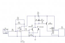
Just for reference, this is the circuit - pretty obvious implementation really.
There is no gain simply because with my PC's sound output, it's not needed. It doesn't really need voltage gain - what it needed was current gain... the onboard sound will not drive a 32 ohm load without some current limiting kicking in and distorting badly.
An externally hosted image should be here but it was not working when we last tested it.
There is no gain simply because with my PC's sound output, it's not needed. It doesn't really need voltage gain - what it needed was current gain... the onboard sound will not drive a 32 ohm load without some current limiting kicking in and distorting badly.
That was my other thought - simply add a DC offset protection circuit in the same manner as a power amp. I didn't know how effective this would be for a low output circuit like a headphone amp though.
During testing a good practice is to add a capacitor with the load.
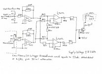
I know this is not acceptable, soundwise, so I have simulated a simple modification of a power amp Dc protection, for HeadPhones.
It'll trigger the relay for DC offset or +-65mV or more.
It's not tested so there may be errors. Could be done better I quess but I can not thing anything simpler than that.
Attachments
How about driving the headphone symmetrically? That may require re-wiring though. But if one supply goes the outputs will swing to the same level, no DC across the headphones...
just my two cents
PS: Nice circuit by the way.... Thinking about doing something similar for my K701's
just my two cents
PS: Nice circuit by the way.... Thinking about doing something similar for my K701's
How about driving the headphone symmetrically? That may require re-wiring though. But if one supply goes the outputs will swing to the same level, no DC across the headphones...
just my two cents
PS: Nice circuit by the way.... Thinking about doing something similar for my K701's
Common ground so not really possible. I think a regular relay based DC detect will do the job.
The circuit works pretty well. I only used those MJE15032/3 transistors because I had them - BD139/140 will probably work just as well, although they are biased fairly high so the TO-220 package probably works well here.
Here's a picture of the murderer!
An externally hosted image should be here but it was not working when we last tested it.
I am building such a device. At least it is on a to-do list.
I will use an Atmel microcontroller to control and TL08x opamp for sensing.
Relay (OMRON G6K or similar) for switching.
Some say the MCU can fault too but then the system wont turn relay on.
Main advantages (or possibilities):
-can sense PSU voltage and react depending those
-can sense DC on output and react depending those
-could sense temperature and react depending those
-can be used to StandBy mode and switch the main power for amplifier (if has different transformer and 230V relay)
-can be controlled by push buttons
-can drive LED for feedback or even display
-can built SMT, no big caps needed but relay drive transistor
-few parts
Controlling ideas:
-can sense DC levels, triggering level can be set precisely
-can wait and see if DC shows up again and decide
-can set alert levels depending on faliure (short turn off, long tudn off, turn off and wait for interact)
-can send signal (LED) to interact if needed
-of course it can be programmed for turn on delay and check DC before turn on.
-possibilities are endless but restricted on MCU ports (legs)
Disadvantages:
Need different power supply. It needs 5V, but draws only 50mA (with relay) I think, maybe can be connected to the positive transformer rail with a 5V regulator.
What do You think?
Of course I would publish all files if there is an interest.
Last edited:
All amps should have some kind of battery offset/supply error based shutdown.
I like the micro controller idea for a few reasons.
1. Your power switch can be the micro controller power switch. It can be in charge of turning on the amp and switching the output relays.
2. It can easily run a shutdown routine that will switch off the output and then shutdown the amp.
3. It can monitor the rails in real time. Threshold shutdown..
It also sucks for a few reasons.
1. It's expensive.
2. Needless excess.
3. While space and battery life isn't a concern in a desktop amp. It is in a portable.
There is a need for a competent design for something that is in charge of the condition of the battery/supply. Ground channels and rail splitters are like using a sledge hammer for finishing nails. I have always thought this was a better solution.
If you use 'phones designed to the IEC recommendation for a 120 Ohm source impedance (Senns, most Beyers etc), then simply using that 120R in series with the output will probably prevent this off +/-12v supplies.
Into 120ohm phones you'd get 0.25W dissipation - slightly outside most phones 200mW maximum, but very likely survivable (use 1/8w resistors and they will smoke first!) Higher impedance phones would see slightly more, low impedance phones rather less. Unfortunately it is low-impedance phones that often require a lower output Z to shine.
Just a thought...
Yeah I thought that. In sim I got a dramatic rise in THD with the 120 ohm resistor, and the amp sounded better without it. The Beyers are rated for 50mW max.
Mine got hit by 1.8W if I've calculated correctly! I'm surprised the voice coils are even intact - the 'phones still work but they sound absolutely awful now, especially the right channel. I knew I was screwed when i turned it on and they went CLICK.
Mine got hit by 1.8W if I've calculated correctly! I'm surprised the voice coils are even intact - the 'phones still work but they sound absolutely awful now, especially the right channel. I knew I was screwed when i turned it on and they went CLICK.
OK so I have been trying out various DC detect circuits. So far, I haven't found one that's very reliable with low supply voltages - ideally I would like one that trips with only 1V DC as this is plenty to destroy headphones. The biggest problem I have found with most detector types is that they are asymmetrical.. they may trip with +4V for example but then need eg -9V to trip. Not very good.
Any suggestions?
Any suggestions?
I think you would need a purpose designed circuit for this... it's going to end up more complex than the amp itself. And if it does trip what does it act upon... shut the PSU, disconnect the phones?
If you are determined then I think maybe you need to look at a window comparator.
If you are determined then I think maybe you need to look at a window comparator.
I think you would need a purpose designed circuit for this... it's going to end up more complex than the amp itself. And if it does trip what does it act upon... shut the PSU, disconnect the phones?
If you are determined then I think maybe you need to look at a window comparator.
I was going to put a relay on the output as I have plenty of suitable ones - i would also think that at this sort of level, small signal relays would work very well.
I have seen circuits based around opamps and comparators so I guess that is the way to go - i can certainly see how using a comparator with a very low reference voltage would trip quickly, and it could easily be made to latch which would be even better. I've seen allsorts of really curious setups used for the detector - from diodes building a rectifier to transistors in all sorts of odd combinations!
It also sucks for a few reasons.
1. It's expensive.
2. Needless excess.
3. While space and battery life isn't a concern in a desktop amp. It is in a portable.
1. If You call 2$ Expensive (See Attiny 25)
2. It is my hobby, so I do not mind, and it needs no external components to work except the relays and buttons!
3. SO8 package isn't exactly big. Attiny25 works on 1,8-5V and can power from a CR2032 battery for a year if Your program only activates in about every 1s only. (periodic checks, You need a backup battery to use a bistable relay to save energy)
It is really a concept. If there is a better solution with a few opamps or comparators, I will try that too but I am not an expert in those.
Last edited:
You want simple really...
Just ideas... use a relay to short the output across the phones if DC appeared. Use a low value fuse in the rails somewhere. Transistor/IC/FET whatever to turn the relay on when anything DC wise appears... at least 0.7v of course for a simple transistor based detector.
Use FET's instead of relay if the signal is to pass through the relay... recent thread on this, you've probably seen it.
This is a comparator I designed but never built for real other than on a breadboard. If you kept the top input at 0 volts it would have the -/+0.1v trip threshold. It was really designed to compare input/output differential of amp to eliminate the integrator delay.
Do you know what I'd do Jaycee... build your amp on a PCB and accept the risk. If the designs good, components good and build good it's never going to fail is it ?
Attachments
This is a comparator I designed but never built for real other than on a breadboard. If you kept the top input at 0 volts it would have the -/+0.1v trip threshold. It was really designed to compare input/output differential of amp to eliminate the integrator delay.
I'll play with that next but it is pretty much similar to what I was thinking about! I believe the Velleman speaker protector is also similar to this circuit.
I also remembered a comparator circuit of sorts from an Arcam amp. I simplified it a bit and this is how it turned out. It seems to work fairly well.
An externally hosted image should be here but it was not working when we last tested it.
In the above schematic R2 represents the relay coil.
An externally hosted image should be here but it was not working when we last tested it.
Notice the relay is across both supplies - so if one supply fails, the relay will shut off anyway!
Do you know what I'd do Jaycee... build your amp on a PCB and accept the risk. If the designs good, components good and build good it's never going to fail is it ?
Never say never! Though yes, in this case the amp only "failed" because it was on breadboard. I should have at least built it on Veroboard I suppose. I was working on a PCB layout but have little free time, and now the money that was going to pay for the case, toroid etc is going to have to be spent on new headphones
- Status
- This old topic is closed. If you want to reopen this topic, contact a moderator using the "Report Post" button.
- Home
- Amplifiers
- Headphone Systems
- Protection on headphone amps