Mark suggested that I chronicle my mini-console project. It is based (speaker wise) on the first generation CHR-70.
Some background:
It is my plan to make a special gift for each of my eight grand children as close to the high school graduation as possible. The first was a guitar amp for my grandson based loosely on the Marshall 18 Watt with a modified plexi front end. The project I am discussing here is the second project which is a mini-console iPod dock for my grand daughter.
The concept is to take the vacuum tube console stereo concept and shrink it down as small as possible while still retaining full spectrum high quality sound but still have it portable enough to move from room to room. It is not to be a portable in the sense of a ghetto blaster but in the sense of easily transportable. It compares to the traditional iPod dock in much the same way that the original Compaq Luggable compares to a notebook.
The design is still in flux and has been discussed in several other places in one form or another.
Electronics and some amp build here...
http://www.diyaudio.com/forums/tubes-valves/180141-mini-console-schematic.html
Some Layout possibilities here...
http://www.diyaudio.com/forums/tubes-valves/176015-layout.html
Laborious process of settling on an approach here...
Serious design effort begins on mini-console project - AudioKarma.org Home Audio Stereo Discussion Forums
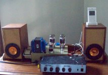
In the end I decided on a SE KT-88 amp in UL mode with Schade local feedback. The Power amp has been built and has been used in testing various speaker possibilities.
Now for the speaker part:
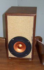
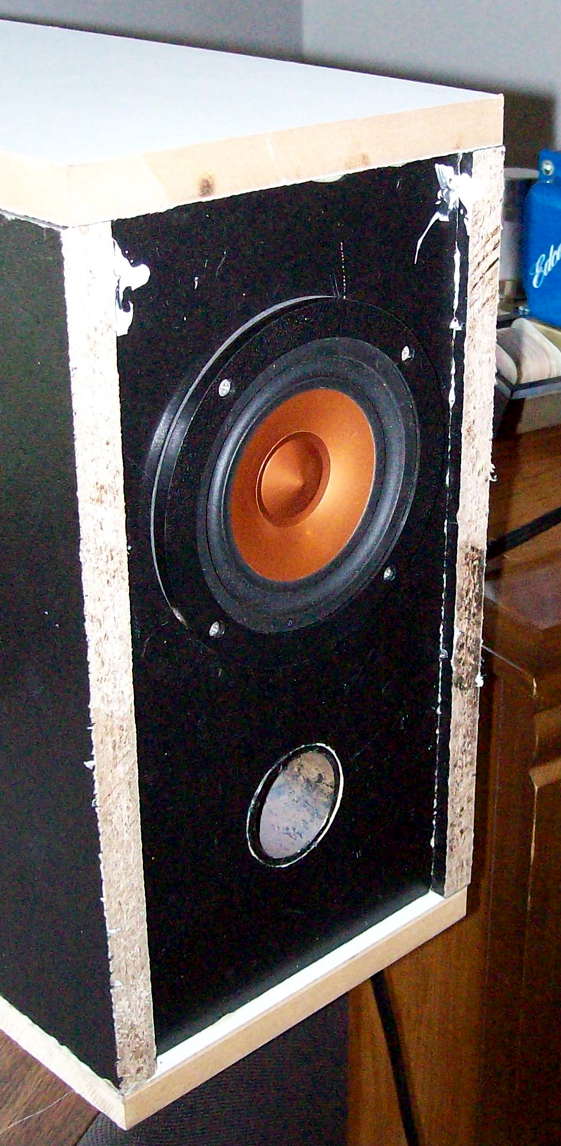
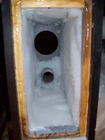
I started by putting the drivers in a hacked up Onkyo cabinet which is very small and sealed just to get an idea of the sound and capabilities.

They sounded quite good with exceptional imaging and plenty of volume. The mixer that I am using for testing does not have enough gain to drive the amp to full output but still provides very loud listening levels.

It was lacking in bass so I looked into doing a ported box to get down to my goal of usable output to 40Hz. It looked feasible...

So I built a test box. (To be Continued)...
Some background:
It is my plan to make a special gift for each of my eight grand children as close to the high school graduation as possible. The first was a guitar amp for my grandson based loosely on the Marshall 18 Watt with a modified plexi front end. The project I am discussing here is the second project which is a mini-console iPod dock for my grand daughter.
The concept is to take the vacuum tube console stereo concept and shrink it down as small as possible while still retaining full spectrum high quality sound but still have it portable enough to move from room to room. It is not to be a portable in the sense of a ghetto blaster but in the sense of easily transportable. It compares to the traditional iPod dock in much the same way that the original Compaq Luggable compares to a notebook.
The design is still in flux and has been discussed in several other places in one form or another.
Electronics and some amp build here...
http://www.diyaudio.com/forums/tubes-valves/180141-mini-console-schematic.html
Some Layout possibilities here...
http://www.diyaudio.com/forums/tubes-valves/176015-layout.html
Laborious process of settling on an approach here...
Serious design effort begins on mini-console project - AudioKarma.org Home Audio Stereo Discussion Forums
In the end I decided on a SE KT-88 amp in UL mode with Schade local feedback. The Power amp has been built and has been used in testing various speaker possibilities.
Now for the speaker part:
I started by putting the drivers in a hacked up Onkyo cabinet which is very small and sealed just to get an idea of the sound and capabilities.
They sounded quite good with exceptional imaging and plenty of volume. The mixer that I am using for testing does not have enough gain to drive the amp to full output but still provides very loud listening levels.
It was lacking in bass so I looked into doing a ported box to get down to my goal of usable output to 40Hz. It looked feasible...
So I built a test box. (To be Continued)...
Attachments
Cobbled together a 1/2 cubic foot ported enclosure from scraps on hand and lined it with poly batting...

It worked quite nicely and extended the response solidly below 50Hz but 4" just seemed like it was working awfully hard to get the output.
MiniConsole Speaker Enclosure Beta Test - YouTube
I discussed it a bit in this thread...
http://www.diyaudio.com/forums/markaudio/193247-alpairs-arent-woofers.html
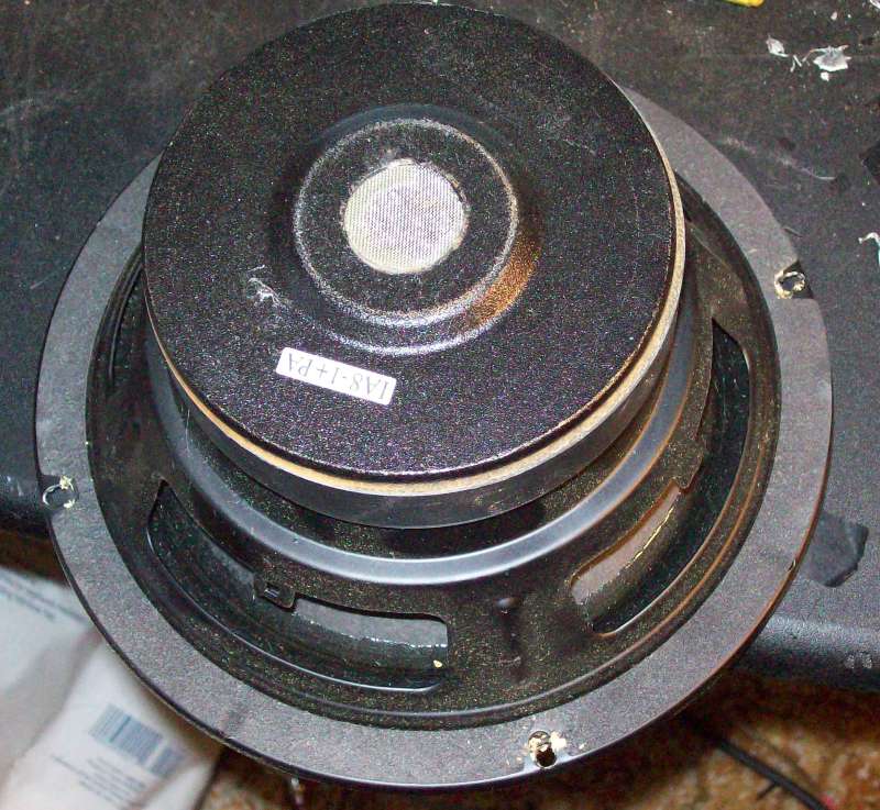
So I decided that since this would be used by a young person that I should provide more margin by using helper woofers. I looked at some possibilities like the 6.5" Shielded Dayton Classic and it looked like it would be helpful but when I looked at the cost of adding the drivers and a passive crossover at 100Hz or so I started to think about going back to my original intention of including an integral powered subwoofer instead of just providing the sub output for an external one.
Other than microphonics my main concern had been the added cost and weight of the integral sub. I went back and looked at an 8" subwoofer driver that I had on hand. It was removed from an AR powered sub that I got over 15 years ago and so I dismissed it out of hand as too old to be used in a gift. I took a look at it today and I am having second thoughts.
I had assumed that the surround would be getting long in the tooth but as I look at it it I see no indication of deterioration and I am tempted to give it a try. Buying a small plate amp would really cost no more than the passive crossover and if I didn't have to buy the driver too... maybe.

By using the powered sub I could use a very small sealed enclosure for the CHR70s thus providing some mechanical protection from over excursion and then roll in the sub at about 100Hz.
I am still looking at some other drivers I have on hand for a passive solution and would sure welcome your thoughts on the subject.
It worked quite nicely and extended the response solidly below 50Hz but 4" just seemed like it was working awfully hard to get the output.
MiniConsole Speaker Enclosure Beta Test - YouTube
I discussed it a bit in this thread...
http://www.diyaudio.com/forums/markaudio/193247-alpairs-arent-woofers.html
So I decided that since this would be used by a young person that I should provide more margin by using helper woofers. I looked at some possibilities like the 6.5" Shielded Dayton Classic and it looked like it would be helpful but when I looked at the cost of adding the drivers and a passive crossover at 100Hz or so I started to think about going back to my original intention of including an integral powered subwoofer instead of just providing the sub output for an external one.
Other than microphonics my main concern had been the added cost and weight of the integral sub. I went back and looked at an 8" subwoofer driver that I had on hand. It was removed from an AR powered sub that I got over 15 years ago and so I dismissed it out of hand as too old to be used in a gift. I took a look at it today and I am having second thoughts.
I had assumed that the surround would be getting long in the tooth but as I look at it it I see no indication of deterioration and I am tempted to give it a try. Buying a small plate amp would really cost no more than the passive crossover and if I didn't have to buy the driver too... maybe.
By using the powered sub I could use a very small sealed enclosure for the CHR70s thus providing some mechanical protection from over excursion and then roll in the sub at about 100Hz.
I am still looking at some other drivers I have on hand for a passive solution and would sure welcome your thoughts on the subject.
Attachments


Last edited:
you could put the CHR70 in 2 liters seald, and add a series capacitor of 680µF to flatten the response and to protect from low bass. this should give an f3 of 80Hz-ish.
some correction of the baffle step might be usefull (1 single RCL will do the trick), if I look at the cabinet size you have, it appears the same as a design I made, there I needed to lower the output around ~1kHz some 3dB to make it sound more neutral. But in a doc this frequency might be somewhat lower
some correction of the baffle step might be usefull (1 single RCL will do the trick), if I look at the cabinet size you have, it appears the same as a design I made, there I needed to lower the output around ~1kHz some 3dB to make it sound more neutral. But in a doc this frequency might be somewhat lower
Thanks Henkjan.
One of the problems that I am having is that in most alignments I have simulated there is a fairly broad area in the vicinity of 60 to 120Hz where maximum output is Xmax limited followed by a segment where it is power limited and then at the very bottom of course it is Xmax limited again.
What I was hoping for is an alignment where the Xmax limited region was contiguous for easy efficient filtering. In general it appears that a sealed configuration as you suggest is the only one that gives me that behavior. Unfortunately I start getting Xmax limiting at a rather high frequency (around 120Hz typically) and of course the resulting output level is much lower.
Ported alignments don't seem to be very well behaved for the amount of gain that I get however several TL approaches looked promising. Some time in the next few days I will try to get around to rerunning some of the sims and saving the results to post here. One of the most promising was a TL tuned to around 70Hz IIRC. The output levels shown were much higher than the sealed (and even higher than the ported).
If I am remembering correctly it was approaching 100dB in the pass band at just a couple or three watts. I estimate the amps capability at around 8 watts but again in the bass we are Xmax limited to this level. Of course stuffing and the real world will probably shave off some of that output but that should still be adequate.
Going strictly from memory it was a 120cm long tapered line with the closed end at 150cm^2 and the terminus at 50cm^2 driver located 1/3 of the way from the closed end. After converting to inches it looks to me like a two fold (three segment) line of this length should be small enough to work.
IIRC the response begins rising at around 120Hz till the tuning point of around 65 or 70 Hz where it is about 3 or 4dB higher and the of course drops precipitously. If the filtering were placed correctly I suspect that we could get the response to be essentially flat down to the tuning frequency. I could use passive first order in combination with the second order line level filtering to get ultimately a 3rd order response for additional protection.
I have been able to get nice looking responses with longer TLs down to 50Hz or lower but I don't like running it that low as you simply must have a lot of displacement to get usable volume (thus the subwoofer) and the size gets to be problematic.
I ran some simulations on the subwoofer in a TL (it would be in a separate box I think at this point to make its use optional and to retain portability as well as of course limiting the microphonics issue). I measured the parameters that I could some time ago and then guessed at some based on the factory enclosure and its performance therein. Using those parameters it looks like solid 100dB performance down to 30 or 35Hz should be doable in rooms of the size for which it is intended.
I will still keep the sealed approach in mind if my experiments with other approaches do not pan out.
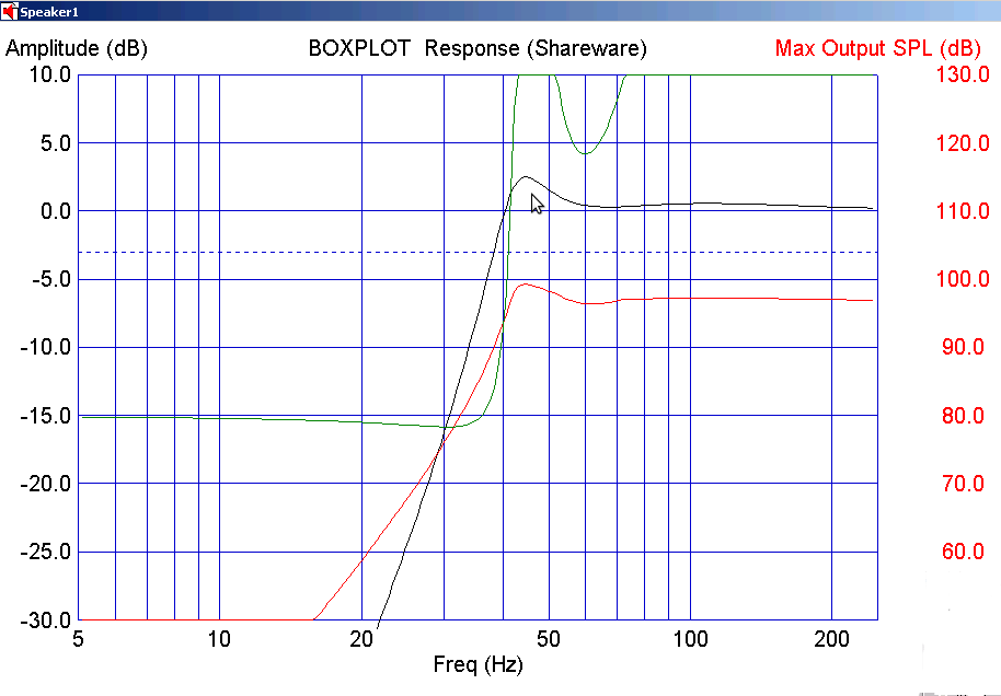
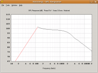
OK, got energetic. ") Will compare 10 liter sealed with 3:1 TLs of length 98, and 120cm in length. I did sims at 108cm also but forgot to save some of the screen shots. Results were intermediate between these two however.
Will compare 10 liter sealed with 3:1 TLs of length 98, and 120cm in length. I did sims at 108cm also but forgot to save some of the screen shots. Results were intermediate between these two however.
Will look first at 1 watt response graphs.
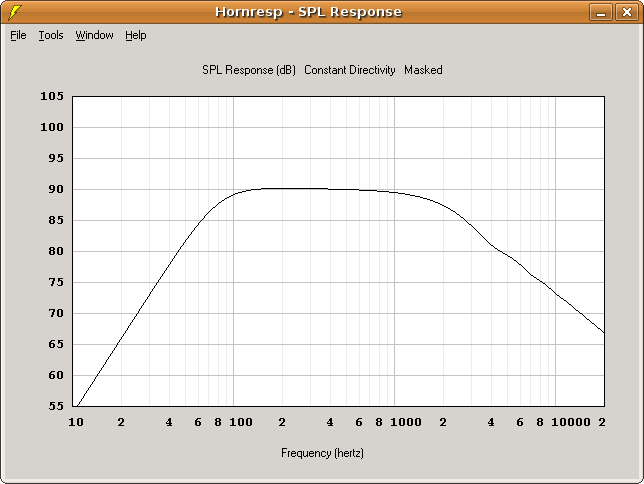
Clearly we gain a few dB of efficiency out of the TL and even in the shortest one we have useful output to 60Hz and even 50Hz in the longer line. Below 100Hz the sealed box is rapidly losing ground. It rolls of more slowly of course but to make use of that fact would require large amounts of EQ. which would stress the amplifier and no doubt destroy the drivers.
Next we will compare maximum SPL.
Will compare 10 liter sealed with 3:1 TLs of length 98, and 120cm in length. I did sims at 108cm also but forgot to save some of the screen shots. Results were intermediate between these two however.Will look first at 1 watt response graphs.
Clearly we gain a few dB of efficiency out of the TL and even in the shortest one we have useful output to 60Hz and even 50Hz in the longer line. Below 100Hz the sealed box is rapidly losing ground. It rolls of more slowly of course but to make use of that fact would require large amounts of EQ. which would stress the amplifier and no doubt destroy the drivers.
Next we will compare maximum SPL.
Attachments
Last edited:
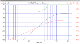
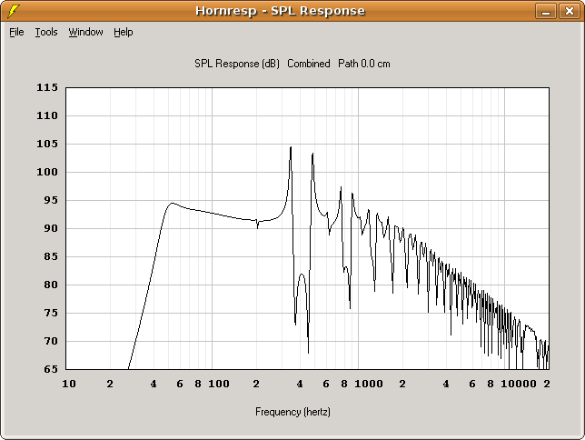
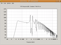
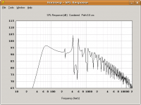
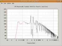
Here we look at the maximum SPL with 8 watts and 3mm Xmax available. Again order of screen shots is 10l sealed, 120cm TL and 98cm TL. NOTE: the segments in red are Xmax limited.

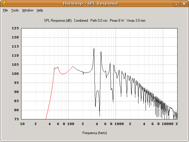

Both of the TLs provide higher maximum output all the way down to 60 Hz than the sealed can do at around 100Hz. The longer line holds 100dB all the way down to 50Hz. The shorter line give higher output all the way down to 60Hz than the sealed can do at any frequency given the limited power available.
With the tip up in response that the TLs provide we should be able to provide enhanced performance and acceptable safety margins with proper application of filters.
Right now I tend to favor the shorter line for its higher overall output (reducing the temptation to push its limits) and the greater up turn in response which allows for more aggressive filtering.
Attachments
Last edited:
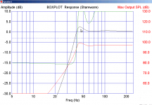
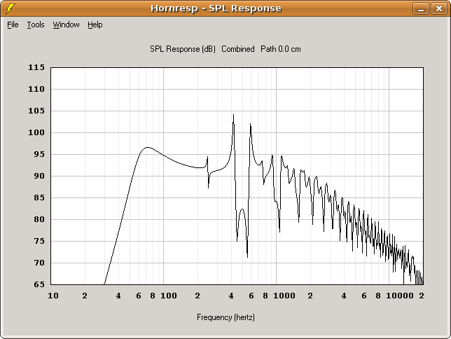
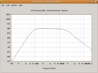
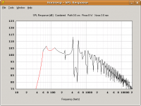
And just for giggles a look at the subwoofer in a 30Hz line.

Nice smooth output down to 30Hz (good enough for the 16' pedal stops even if we miss the 32s). Guessing at 8mm Xmax it is holding 112 dB down to the cutoff. I just guessed at Xmax on this driver but I think that is a conservative estimate. Output could go higher if I am underestimating.
Will have to see how it acts in the real world.
Nice smooth output down to 30Hz (good enough for the 16' pedal stops even if we miss the 32s
). Guessing at 8mm Xmax it is holding 112 dB down to the cutoff. I just guessed at Xmax on this driver but I think that is a conservative estimate. Output could go higher if I am underestimating.Will have to see how it acts in the real world.
Attachments
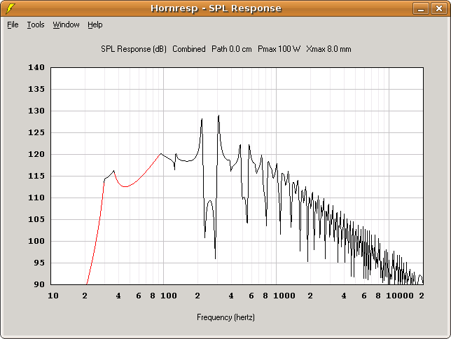
Oh, I almost forgot. Just for fun I ran sims at 150cm for the MA driver.


It can get down there to 40Hz but it just takes too much out of the little fella and maximum output just goes down too far for anything but easy listening me thinks.
It can get down there to 40Hz but it just takes too much out of the little fella and maximum output just goes down too far for anything but easy listening me thinks.
Attachments
A question on baffle step
In looking at the two possibilities (helper woofer and separate sub) I thought to look into the baffle step issue. As I understand it the baffle width is the dimension that is in question regardless of driver offset so that it is not the first surface that is reached by the sound wave that causes it.
Since both channels are mounted on the same baffle (console) is the entire width of the console considered the baffle width? If so this would be mighty convenient as the nearly 3 feet of baffle would put the critical frequency right at the 100-150Hz range where I want to cross to helper woofers. In that case I would just need to use a woofer that is about 3dB more efficient than the MA driver.
But, it seems to me that since the height is less than the width that the height of the console might be the actual baffle width in this instance.
Some guidance would be appreciated.
I don't have a drawing but think of it as your fathers console stereo shrunk down so that it will fit on top of a dresser. About three feet wide maybe 18 inches deep and about that tall.
Hi M,
I think I see what you mean. If I've understood correctly, I'd urge you to make separate driver compartments so the CHR's cone's don't get pressurised by the woofer. Or is the woof going somewhere else. Maybe I'm still not quite seeing the whole idea?
Thanks
Mark.
Thanks guys. My thought was to make a small sub compartment for the FR of about 5 liters as suggested earlier in the thread.
I ran some simulation on both the Aura NS6 and NS8 and it looks to me like both could work in a ported enclosure of 1 ft^3 (30 L) or somewhat less tuned to 45 or 35 Hz respectively. The 6" shows higher overall output per watt (in fact possibly a bit too much) but the 8" goes lower and has a sensitivity that seems much more appropriate for the CHR70.
Hornresp simulations show the 8" about 3 or 4 dB higher than the midband output of the CHR70 where the 6" was simulating at least 6 dB higher. I can control this somewhat with cabinet size but with the 6" I start to get really significant early roll off when I do that.
Aurasound NS6-255-4A 6" Paper Cone Woofer 4 ohm: Madisound Speaker Store
Aurasound NS8-385-4A 8" Woofer: Madisound Speaker Store
I figure a 9mH inductor and 250uf NP electrolytic should give me a crossover right around 100-110Hz which should mate up well with the FR. Would it be advisable if I put a series NP cap on the FR to use a couple uf film cap to bypass it for better mid and hf clarity?
I am also considering using some sort of flameproof foam board insulation on the bottom and sides of the amplifier compartment to help keep microphonics under control by damping out vibrations from the speaker cabinets before they get to the amp and preamp chassis. Any thoughts on that?
Last edited:
TL looks good I would go for the lower tune though if its for a young person as when it does get high amplitude low stuff its more likely to survive instead of giving the impression that it's doing ok until the low note hits on a higher tuned line. Any chance of more info on the lines I am potentialy thinking of some new boxes and the performance looks good!
Just wondering what you guys think of this idea for insulating the amplifiers from the speakers.
My thought was to build the speaker enclosures from 1/2" or so OSB with internal bracing. Then line the part of the console where the speakers will be with thin foam insulation panels with the enclosures sized to be a snug fit in the resulting cavity. The top front bottom and one side of the cavity would be a part of the console body. Separate side and back pieces made from the same wood as the console (probably 1" poplar boards) also lined with the foam board would be pressed tightly against their respective sides and securely attached to the console body.
Thus we would have the entire OSB enclosure encased in a foam and solid wood sandwich. The hope is that this would minimize the vibrations transfered to the console body on which the amps are mounted. I could still mount the chassis with damping material between them and the console body also to insulate them from any vibration that does make it into the console body.
Thoughts?
After soliciting some advice and some careful consideration I think that I will build the enclosure into the console and isolate the electronics instead so that the enclosure can be as rigid as possible.
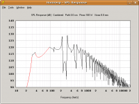
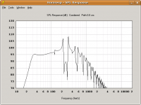
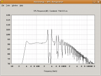
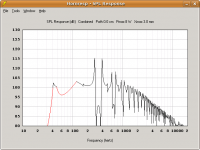
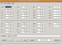
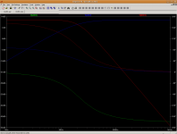
I got the parts for a passive crossover using 2nd order on the woofer and first order on the FR which brings up the issue of phase. If both drivers are using 2nd order than one usually inverts one however in this case it is somewhat less clear.

The dotted red line is the phase of the woofer when inverted and the green is with it connected in the normal fashion. If connected inverted the remaining output from the woofer above the crossover point is in phase with the FR and would add to the output in that region. If connected "in phase" it would be 180 degrees out of phase and subtract.
In either case the phase below the crossover is about 90 degrees out of phase no matter which connection is used. So in the bass region the resultant is probably going to be about the same so the choice comes in how we want it to behave above the crossover.
At first blush it might seem that one would want the phase equal so that the sound is as coherent as possible in the mid range, however, given that a TL enclosure will probably be used for the woofer the spikes and valleys that remain would either add or subtract from the overall output.
So in the end I might just need to try both connections. I have not yet purchased the woofers (next paycheck) but I will probably go ahead and build the crossover today or tomorrow and play around with some woofs that I have on hand.
I will post as it progresses.
I got the parts for a passive crossover using 2nd order on the woofer and first order on the FR which brings up the issue of phase. If both drivers are using 2nd order than one usually inverts one however in this case it is somewhat less clear.
The dotted red line is the phase of the woofer when inverted and the green is with it connected in the normal fashion. If connected inverted the remaining output from the woofer above the crossover point is in phase with the FR and would add to the output in that region. If connected "in phase" it would be 180 degrees out of phase and subtract.
In either case the phase below the crossover is about 90 degrees out of phase no matter which connection is used. So in the bass region the resultant is probably going to be about the same so the choice comes in how we want it to behave above the crossover.
At first blush it might seem that one would want the phase equal so that the sound is as coherent as possible in the mid range, however, given that a TL enclosure will probably be used for the woofer the spikes and valleys that remain would either add or subtract from the overall output.
So in the end I might just need to try both connections. I have not yet purchased the woofers (next paycheck
) but I will probably go ahead and build the crossover today or tomorrow and play around with some woofs that I have on hand.I will post as it progresses.
Attachments
- Home
- Loudspeakers
- Full Range
- Mini-console based on CHR-70 gen1