Hi @all
i'm new to tubes and planning my first project. So i did a good read in literature and did some spice simulations to get a better understanding.
The project is a 2 stage interstage-coupled KT88 PP amp (see attachment). But there are some things related to the interstage transformer which i didn't understand. Hopefully someone can help me out?!
I know that transformer-modells in spice are somewhat limited and it's hard to get the needed data from manufacturers. Elsewhere i read as a rule of thumb that the impedance of the IT should be 3 times the internal plate resistance of the driver.
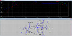
5842 has a plate resistance around 1,6-1,7k. If i use the model for an 1:1+1 IT with 5k impendance (primary) i get an bump on the secondary in the area
around 1800 Hz. This can only be cured if i place two resistors on the secondary to center ground which have an value 10-20k which lowers the gain. Are there any other downsides if i use the resitors?
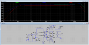
If i use instead a IT with a lower impedance like the lundahl 1660 (3.5k) than the 1,8k-bump disappears.
So how to select the impedance of a IT? Or is the bump irrelevant cause it's canceled out due to opposite effects on the secondarys?
Another question: I've read that the inductance of the IT determines the lower frequency response. If i understand it correctly the IT should have an Inductance of min 13,5H to reach 20HZ with an 5842 (1700/2*pi*20).
Thanks in advance
Galac
p.s. I've attached the screenshots from the spice simulation for better understanding. green/blue are the secondarys - red is taken from the OPT. i did not attach the version with the 10-20k resistors on the secondarys cause it looks like the lundahl version without the rise around 250k.
i'm new to tubes and planning my first project. So i did a good read in literature and did some spice simulations to get a better understanding.
The project is a 2 stage interstage-coupled KT88 PP amp (see attachment). But there are some things related to the interstage transformer which i didn't understand. Hopefully someone can help me out?!
I know that transformer-modells in spice are somewhat limited and it's hard to get the needed data from manufacturers. Elsewhere i read as a rule of thumb that the impedance of the IT should be 3 times the internal plate resistance of the driver.
5842 has a plate resistance around 1,6-1,7k. If i use the model for an 1:1+1 IT with 5k impendance (primary) i get an bump on the secondary in the area
around 1800 Hz. This can only be cured if i place two resistors on the secondary to center ground which have an value 10-20k which lowers the gain. Are there any other downsides if i use the resitors?
If i use instead a IT with a lower impedance like the lundahl 1660 (3.5k) than the 1,8k-bump disappears.
So how to select the impedance of a IT? Or is the bump irrelevant cause it's canceled out due to opposite effects on the secondarys?
Another question: I've read that the inductance of the IT determines the lower frequency response. If i understand it correctly the IT should have an Inductance of min 13,5H to reach 20HZ with an 5842 (1700/2*pi*20).
Thanks in advance
Galac
p.s. I've attached the screenshots from the spice simulation for better understanding. green/blue are the secondarys - red is taken from the OPT. i did not attach the version with the 10-20k resistors on the secondarys cause it looks like the lundahl version without the rise around 250k.
Attachments
Hi!
impedance specs for transformers are very misleading an I wish transformer manufacturers would not state them. A transformer does not have an impedance itself. It reflects the secondary impednace to the primary and vice versa. The impedance numbers given by manufacturers are meant as a guideline, there is a wide room for interpretation.
What you need to know from an IT is:
winding ratio promary to secondary
DC handling capability
primary impedance
Based on these you can determine the suitability for your project.
Please note that Lundahl does not state a transformer impedance in the datasheet. The 3.5k you mentioned are the driving impedance for which the frequency response was given.
Also note that you can get the Lundahls for different primary DC current. You need to choose the correct one depending on the current your driver draws.
The Lundahls give a lot of possible combinations how you wire them up since they have multiple primaries and secondaries. Parallel combinations have much lower inductance at higher DC current capability than series connections.
In your case, if you don't need all that gain, I would probably select a 1660S/25mA or 1660S/36mA and wire it 2+2:2.25+2.25
Best regards
Thomas
Thanks for your answers!
I made a mistake. I forgot that i changed the values of the side capacitances in the interstage transformer model for the lundahl to almost nothing but not in the 5k-model. these bumb are caused by the side capacitances and the capacitance from the primary to secondary. In the original model they have been set to 30p, 30p and 40p. Are these values in a realistic range?
Another Questions still remains: how to choose the primary impedance? The same value as the plate resitance or two or three times?
The observations from spice seems to indicate that the higher the impedance the higher the gain (although it seems to be stable between 5k to 10k).
Cheers
As Thomas says, and in my experience, it's not so much a question of choosing the primary impedence, though this would give a general idea. It's a question of matching the primary inductance in Henries to the tube. Examples - 2a3 at 800 ohms plate impedence would be good with 20-30H, 26 with 8.5K ohms plate impedence would be good with 150-200H. I guess you could say that 20H for each 1K would be good to aim for.
Andy
Andy
Hi!
As mentioned: transformers do not have an inherent impedance.
Andys rule of thumb is a good start to choose the transformer primary inductance.
Make sure to have the correct DC rating, othwerwise the transformer will saturate.
SPICE is not a good way to develop an understanding of circuits for beginners. I recommend some basic electronic books on the subject. SPICE can be used to analyse the behaviour of certain circuits, but it never models the complete reality. For example your transformer models will not show any core saturation effects due to DC current.
The impedance your driving tube sees is the resitance which you place across the secondary multiplied by the winding ratio squared. So if your transformer is 1:2 and you terminate each secondary with 5k (10k total), your driving tube will see 2.5k in parallel to the primary inductance. If you terminate your secondary, you can aplly the rule of thumb that the reflected impedance is at least 3 times the plate resistance of the tube. I would actually shoot for higher ratios like 5-7.
I mostly prefer unloaded secondaries, so your driving tube sees an almost infinite impedance parallel to the inductance. This way you get the full mu of the tube as amplification, at least in the mid band.
Best regards
Thomas
- Status
- This old topic is closed. If you want to reopen this topic, contact a moderator using the "Report Post" button.
- Home
- Amplifiers
- Tubes / Valves
- Interstage Transformer Questions