Hi this is my first post but i read on this forum alot.
Basically my left channel has gone dead and my local electronics store quoted me £100 just for parts alone. I don't trust them and they said they'd never heard of hafler and gave me a funny look when I asked them to bias the amp. Anyway I have it back now and I want to tackle it my self. Anyway tomorrow I'm going to see the guy who fixes things there and find out whats round with it. But i'm guess all he's going to do is replace the whole power output module as he said you can only get parts in america?
I have a very basic knowledge I know what component types there are and I can measure most with my dmm and i'm ok at soldiering. I also have the hafler schematics but the output caps are modified i couldn't tell you how.
Assuming it is the power output module should I go through and measure everything to see if its shorted and replace with new parts. Any general electronic repair advice would be great or possibly any books that would be helpful to me for repairing things.
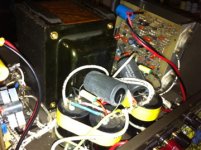
Hafler is more well known in the US than the UK. The schematic is readily available. There are no "output caps" in this amp, it is possible the main power supply capacitors have been replaced. Pictures will help!
If you find that the output MOSFETs have blown... you will have to get a modern replacement as the original Hitachi devices are discontinued. The best replacement is the Exicon devices sold by Profusion PLC. Unfortunately these will not be cheap - probably why you were quoted £100 for parts.
If you find that the output MOSFETs have blown... you will have to get a modern replacement as the original Hitachi devices are discontinued. The best replacement is the Exicon devices sold by Profusion PLC. Unfortunately these will not be cheap - probably why you were quoted £100 for parts.
ye it has four instead of two capacitors and some little extra ones stuck on top joining them together. I heard the mosfets are the least likely thing to blow. Well I'm hoping they will tell me exactly whats wrong tomorrow.
Attachments
So I spoke to the guy at the electronics shop and he said that the left channel was outputing like 5 watts which is wrong and that is it. Apparently they don't need parts from the us that was a lie. He wanted £100 to find out what was wrong with it not including parts so I said don't worry as I paid £120 for it.
So does that 5wats mean anything to anyone? I guess i should test the mosfets. I found these instructions on another thread but I'm not sure if they apply to this type of mosfet.
So does that 5wats mean anything to anyone? I guess i should test the mosfets. I found these instructions on another thread but I'm not sure if they apply to this type of mosfet.
To measure an Nch MOSFET:
1) Use DVM in diode test position
2) Holding red lead on S
3) Put put black lead on D. Reading should be between 500 and 800, you are measuring the forward voltage drop in the body diode.
4) Put black lead on G. Reading should be 1... (open circuit)
5) Hold black lead on S
6) Put red lead on D. You shuld read 1... (open circuit) as the gate should be retaining negative charge from step 4.
7) Put red lead on G, you should read 1... (open circuit)
8) Put red lead backon D, you should read a low value (close to zero initially, possibly rising very slowly). You are now measuring the D-S voltage drop with the gate positively charged in step 7.
In any case, source to gate and drain to gate should alsways read open circuit. If you get low readings in steps 4 or 7, it's dead for sure (in either case, not a MOSFET... any more). If you get low readings in step 3 or 6, there is a good chance it's dead but you can test this later on, by doing it again with G and S shorted. If you get anything but the body diode reading in this case, the FET is dead. Also, you can try to measure the drop between shorted D+G and S, you will get the gate treshold voltage for very small Id provided by the DVM - however, most DVMs don't provide a high enough voltage to get over the gate treshold of VMOS, so you are likely to still measure 1... (open circuit), the exception being lateral MOS (will emasure low, about 1V, useful for testing for fakes), and PI-MOS such as the Toshiba Audio MOSFETs which will measure about 1-2V dependant on DVM.
BTW that schematic for a phones amp cannot work right as the required heater current for the 6922 is 300mA, and the current source connected LM317 only gives 150. It appears to me this was originally designed for a ECC81/82/83 12AU/AX/AT7 type tube with center tapped 12V filament, which is divisible into two 6.3V 150mA filaments by grounding the center tap - but then you have a problem with the too low anode voltage.
Hmm looking at it, someone has definitely modified this amp. The 4 power supply capacitors + bypass capacitors is not stock, but this is an improvement and as long as the supplies are OK, it should be fine.
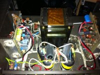
Note that the input capacitor on one board is a new yellow capacitor compared to an older looking blue one. Which one is the faulty board?
Note that the input capacitor on one board is a new yellow capacitor compared to an older looking blue one. Which one is the faulty board?
You will need to join HiFi Engine to pull down the documents - but it's free so go do it.
They have a schematic (hopefully it agrees with yours) as well as the assembly manual. On page 12 of the assembly manual is a voltage chart for checking various values which should help you in finding the problem.......... Hafler DH-220 | Owners Manual, Service Manual, Schematics, Free Download | HiFi Engine
Also - here is a link to trouble shooting amps http://www.repairfaq.org/sam/audiofaq.htm#audaaboco
Last edited:
Don't even need to subscribe to that - It's on the Hafler site http://www.hafler.com/techsupport/pdf/DH-220_amp_man.pdf
edit: just to clarify, the above is not just a "user manual". The early Hafler stuff like this was also sold in kit form, so the manual includes "how to build" and the complete schematic. It also includes voltages at test points, very handy for fault finding.
If memory serves a common fault on these amps is for one of the current sources to fail. This is usually the diodes D1-D6. They are just cheap 1N4148's so easily sourced. Pretty much all of the parts apart from the original output MOSFETs are easily sourced.
Last edited:
Some output devices - but located in US 2SK134 2SJ49 BUZ900 BUZ905 ECF10N16 ECF10P16 EXICON SET | eBay
I do have the assembly manual and schematic but i get those as well in case I'm missing something.
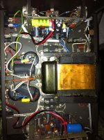
The board with the old blue cap is the left side and that is the one thats not working properly. The right side has some polyester film caps on which the left doesn't. I did start checking all the resistor values and then realised they would be the last to blow.
I will have to reassemble to read voltages as i have the mosfet and heatsink off ready to test them I just need to know the correct way of doing it. Plus I've never measured voltage before so I'll have to figure that out to. Do you know what the capital letters above voltage mean in the manual on page 12?
Should i just check everything on the board on that channel as it's so old? Then all I have left is the mosfets and the power supply caps to check.
Some output devices - but located in US 2SK134 2SJ49 BUZ900 BUZ905 ECF10N16 ECF10P16 EXICON SET | eBay
That doesn't seem to bad around £40 incl delivery not incl import tax
I never recommend such things from eBay as it is the #1 place to sell fakes.
I'd say the right hand channel has been repaired at some point then. It might be worth taking close up pics of both boards to see what the last owner replaced.
The letters are "E" "B" and "C" which means Emitter, Base and Collector - this identifies the pins on the transistors labelled. If you are not familiar with the symbols for transistors, look this up. Also look up the data sheets for the transistors used as this will describe the pinouts.
C1 is the large blue capacitor (or the yellow tubular capacitor on the new board). It will be worth replacing this I feel. Similarly it will be worth replacing the electrolytic capacitors on the board (C12, C14, on the board).
Also worth replacing C8 - this is a "non polar" electrolytic which could be difficult to find. You can use a normal polarised 470uF 16V capacitor - in practice the small amount of DC voltage across the capacitor is not a problem.
Don't even need to subscribe to that - It's on the Hafler site http://www.hafler.com/techsupport/pdf/DH-220_amp_man.pdf
edit: just to clarify, the above is not just a "user manual". The early Hafler stuff like this was also sold in kit form, so the manual includes "how to build" and the complete schematic. It also includes voltages at test points, very handy for fault finding.
If memory serves a common fault on these amps is for one of the current sources to fail. This is usually the diodes D1-D6. They are just cheap 1N4148's so easily sourced. Pretty much all of the parts apart from the original output MOSFETs are easily sourced.
d1 is reading 597 d6 is 598 i'm just going through and checking all the diodes and resisters. Can I use a continuity setting on the dmm to check polyester film and electrolytic cap has blown?
The behaviour you mention is caused by C15/C16 shunting the diode. To be sure you need to measure it out of circuit.
It is unlikely that polyester capacitors will be "blown".You cannot test them with a continuity check, you need to do a capacitance check in this case. Do not worry about the film caps - it is unlikely they are damaged.
It is unlikely that polyester capacitors will be "blown".You cannot test them with a continuity check, you need to do a capacitance check in this case. Do not worry about the film caps - it is unlikely they are damaged.
I do have the assembly manual and schematic but i get those as well in case I'm missing something.
The board with the old blue cap is the left side and that is the one thats not working properly. The right side has some polyester film caps on which the left doesn't. I did start checking all the resistor values and then realised they would be the last to blow.
I will have to reassemble to read voltages as i have the mosfet and heatsink off ready to test them I just need to know the correct way of doing it. Plus I've never measured voltage before so I'll have to figure that out to. Do you know what the capital letters above voltage mean in the manual on page 12?
Should i just check everything on the board on that channel as it's so old? Then all I have left is the mosfets and the power supply caps to check.
1. Before you reassemble (I hope I'm not to late with that) look at the schematic on page 14. Put your multimeter - probe on a ground point (pin 7) and probe the other test points 1 thru 10 (not including 7) and 1 thru E and take notes. Compare the working board with the non working board - the readings should be close - if you find a large difference it could be an important clue in finding your circuit fault.
2. The letters on page 12 - e, b, c, stand for "emitter", "base", "collector", on the regular transistors (look up your transistor type to find the lead configuration) or on the FET's = (s)ource (d)rain (g)gate.
3. Testing FET's - read http://www.passdiy.com/pdf/mos.pdf
4. The voltage test per the manual are with reference to ground (pin 7 of the PWB and where you want the - probe of your DMM) and the test point to be measured - ps take good notes between the known good board and the non-op board.
I hope this helps - and feel free to ask any questions you need help with.
I never recommend such things from eBay as it is the #1 place to sell fakes.
G'day jaycee - I know that your input is well intended - and well taken. However please take the time to read this chaps ad - he was a Project Engineer at Hafler back in the day and I would say that is a source worth checking into. As usual with all items purchased via eBay - buyer beware.
Hello Simbl, back in the '80s, a friend and I made copies of the Haffler DH500, a very similar circuit to the DH 220, both designed by David Haffler of Dynaco fame. As mentioned above, both the Dynaco and Haffler were avalable as kits. As techs, we were asked to assemble a few of these kits for clients but soon realized that if we made a P.C.B., we could effectively make these amps with mostly ordinary bits. We had some "tunnel heatsink" with a fan at the end from an old mainframe computer power supply we had wrecked. It took four TO-3 power devices on each of its four mounting plates, 16 devices in all. So we decided to build some "monster" "Hafflers". What we ended up with was a "DH-800", with 4 pairs of devices a side. We used the highest Id and Vds devices that Hitachi made and fiddled about with David Haffler's driver stage to drive the extra gate capacitance of the extra pair of paralleled output devices. We knew that these F.E.T.s had higher on resistances than the more common bipolar devices we had been using in earlier amps of other designs we had built so we basically decided to parallel more devices, not for sheer brute power but to get the output impedance down and improve the damping factor, however, with a beefy enough power supply higher output power was an additional "desired" consequence.
Sorry about the "second post", I pressed the "enter key" by mistake.
We built three of these "Hafflers" in all, two were sold and the third I still own and use as my second amp. When I was at Uni, studying chemistry, a band came to play over at the University Union, about 100m from the Chemistry Library where I was studying. As the gig got going, the sound was immense, I went over for a closer look and gave up the library study as it was 5pm on Friday anyway, (we call it "beer O' clock here in Tasmania). As I walked across from the Chemistry building to the Union the sound was so powerful it turned my insides to jelly. As I got closer this effect got greater. I finally arrived and started to poke around the stage to see what sort of amps were delivering such power, and that's when I saw it, it was my "Haffler DH800",
driving some "ear bleeder" JBLs. I thought "did I cause this powerful effect?" It was certainly much more impressive than heating a dummy load on the workbench!
Now for some hints on your problem. Fixing an amp, or any piece of electronic gear for that matter, is like having a conversation with someone. You "ask" the piece of faulty gear a "question" by making a measurement, and it "answers" you by whatever result that measurement reads. Now there are basically four kinds of fault,
Physical faults, like dry joints, broken off transistor leads or other wires or physically broken components, such as diodes or resistors broken in half.
Component faults, where components have failed due to thousands of hours of use and being cycled between hot and cold as the gear is cycled between on and off. The components may have been slightly underrated initially.
Design Faults, where the original designer made a mistake or took a cheap shortcut, "built in obsalescence", one might say. AND
Abuse Faults, where a user had pushed the piece of gear outside it's design tolarences or accidently done something to unintentionally damage it.
When a piece of gear lands on your bench, the first "question" you ask it is, "what class of fault is ailling you?" So you inspect it for dry joints, broken wires, damaged components. such as TO-92 transisrors with the centre lead broken right at the point of entrance to the body of the component where it is not obvious, etc, etc.
Next, look for things which have been hot, browned patches of board, oxidized component leads, powdery grey looking epoxy bodies of plastic encapsulated semiconductors, such as transistors and diodes. Look for shorts through the insulating washers beneath TO-3 output devices, their metal bodies should usually be insulated from the heatsink. (In a mosfet amp, like the Haffler. Perreaux or Jands the F.E.T. cans are the source terminals which go to the speaker output via some low value source resistors, so if a device shorts to the hearsink, it effectively shorts the speaker terminals.)
You won't have to worry about design faults, David Haffler was an honest, straight shooting sort of guy and he designed is circuits very reliably and used over rated bits.
This leaves abuse faults, like acidently shorting the speaker terminals while a loud passage is playing through the amp, plugging in an RCA jack into the input from a piece of gear like a CD player which is turned on, plugged in, not earthed and has a large "float voltage" on it damaging the input devices of the amp. (Typical float voltages are something like 125v (half mains) with a source impedance anywhere from an annoying 1 meg ohm plus, down to a downright dangerous 10 kilo ohms) depending on the design of the signal source piece of gear. RCA jacks have the annoying design flaw which connects the signal before the earth, whereas well designed connectors, such as the XLR, make sure the earth line is connected first equalizing any float voltages between the two pieces of gear, before the sensitive signal path is connected!
So abuse faults are not immediately obvious and damaged (due to overvoltage) input transistors will look exactly like good ones. Sometimes doing something like shorting the speaker terminals of an amp while on will lead to a cascade of spectacular failures, such as output devices shorting and emitter or source resistors catching on fire before the fuse blows...but this is dependent upon the specific circuit design.
I remember accidently shorting out the 8 ohm dummy load, a speaker substitute which makes no noise, a cartwheel of paralleled 56 ohm 5 watt resistors in a cup of water (which we got to boil), while testing one of the "Hafflers" at the full 800 watts R.M.S. with a 1KHz sinewave input from the signal generator. I saw the arc, heard the 1KHz squeal from it, but the amp held up. Bipolar output devices would have "gone to Heaven" instantly, but these "new" MOSFETS took it in their stride.
O.K. Now you know the classes of fault type, you must start asking the amp "questions". The first of which takes the form of a careful visual inspection for dry joints, broken wires or components, components all against heatsinks with enough heat conductive paste or appropriate "snotty grey rubber washers" and areas which have run hot.
Once this has been done, fix any faults found. i.e. clean transistor and put new heat conductive paste on it and firmly thermally couple it to the heatsink, resolder any broken wires, but be absolutely sure where they go!!!!! Use the circuit diagram to work it out. With electronics, NEVER NEVER NEVER GUESS, ALWAYS KNOW , with 100% certainty before taking action. When replacing transistors, make cretain which leads are the base, collector and emitter because often the more modern replacement has a different pinout. Make sure you are not placing a PNP device where an NPN should be and visa versa. Have the data sheets for the old and new devices up on the computer or on paper beside you before you commence replacement of substitution. Check that diodes are in the circuit the correct way around.
One way I familirize myself with a strange circuit, is to draw the circuit diagram directly from the piece of gear. Now not everyone feels they can do this, but if you "bite the bullet" it will reveal absolutely everything that is wrong. If someone has fiddled with it before you and put transistors in back the front, or the wrong polarity, this will reveal it. In drawing the circuit, you must look at and inspect every circuit node, so physical faults will be seen and notes to that effect made on the developing hand drawn circuit....."dry joint under collector of current sink transistor',.....'not enough thermal goo between vbe multiplier transistor and heatsink"...etc, etc.
Those capacitors which are different between the two channels, drawing the circuit will reveal where they are and partially why they were put there. One thing which is worth a look is the feedback network. A Hi-Fi or Pro Power amp is basically like a giant op-amp, but with a much lower output impedance. Almost all audio power amps use a unity gain DC feeback path, with a few exceptions, such as the Luxman 5L15 or 5M21, which simply have two resistors in the feedback and are DC amps. If you look up "op amp" on Wikipaedia, you well see the symbol is a small isosoles triangle on its side. The sharp end is the output and the vertival side has two connections going in, marked - and +. These are the inverting and non-inverting inputs respectively. The Haffler is simply a real big one of these. The + (non inverting) input of the Haffler goes back to the input jacks on the rear panel but the - (inverting) input goes to the speaker output via an AC potential divider consisting of a series resistor between the speaker node and the - input node (on the circuit diagram, the base of one of two mirrored transistors at the front end), and a shunt resistor in series with a capacitor to ground. The ratio of these resistor values will set the amount of feedback, and hence the voltage gain of the unit as a whole.
Reducing the value if the series resistor, from 33k to 27K say, will increase the feedback and decrease the overall voltage gain. (So if she clips on your CD player with the volume control at "3 o'clock", changing the series feedback resistor down will move that position on the volume pot more toward "5 O'clock" before she clips, all other things being the same. Now the shunt capacitor is placed there to give the amp unity gain at DC, because it is a difficult and exacting task to design an amp for DC which does not slowly drift. The capacitor has in 'infinite resistance' at DC, but this decreases as the frequency rises. (XC = 1/2pi.f.C), so as the frequency rises, it divides the feedback voltage more, increasing the gain. This capacitor is usually quite a large value, c100-500uF, to give the amp appreciable gain at low bass frequencies. To get such a large value only an electrolytic capacitor can be used, which is a polarized capacitor which is usually placed across a DC voltage of the correct polarity. (The main filter capacitors in the Haffler's power supply are electrolyrics with a capacity of around 10,000uF at 100 odd volts.) This feedback capacitor, however, has a divided down version of the speaker output across it, effectively pure AC. So many designers resort to a "strange beast" in this part of the circuit, a bipolar or non polarized electrolytic capacitor. From an audiophile point of view the 'musicallity' of such a capacitor is dubious and it is in an important 'signal path' part of the circuit unlike the huge electrolytics in the power supply. Audiophiles cannot avoid such a capacitor though because of its required high capacitance for the bass rolloff response of the amp so the will often bypass it with a high quality, low value film capacitor. Nichicon make a bipolar electrolytic capacitor specifically for this purpose and mark it "MUSE" on the can. In our Hafflers we simply got two ordinary polarized electrolytic capacitors and placed them 'back to back' in series. We used twice the value required in the circuit because two in series devide the capacitance in half. So we put either positive to positive or negative to negative, all that mattered was that the two polarized electrolytics faced in opposite directions, a good quality film cap with about 1/100th to 1/1000th the value of the electrolytics was then placed in parallel with the whole lot and this caboodle stuck into the feedback path between the input earth and the cold end of the feedback shunt resistor.
Now if this feedback capacitor in your Haffler has dried out, its value will have gone high , maybe completely open circuit, in which case the voltage gain of your amp will have dropped nearly to unity across most of the audio spectrum, (so the voltage you feed in at the input will be the same as what appears at the speaker terminals, but the driving imprdance will still be very low and uneffected), there may still be some gain at the top end due to what is left of the dried out cap, so that channel will sound "weak and tinny".
Your options are...
Source any old bipolar cap locally and bypass it with a film cap....
Put two high quality, ordinary polarized electros of twice the value back to back anf bypass it with a good film cap as described above....
Go to E-Bay and try to get some Nichicin "MUSE" bipolars and bypass them with a film cap.
Don't be to pickey with the values, if your'e a bass junkie like me, the bigger the value the better, i.e. the lower the -3bB bass rolloff knee of the amp. The voltage ratings of these feedback caps is not great, usually in the 6.3 to 16 volt range. the higher the rating the less prone to failure and drying out but the bigger the can will be and you may have trouble getting it in amongst the other bits on the board. As a rough guide, use two 470uF, 16v ordinaty elecrtos, back to back as a cheap fix, bypass it with a 100-470nF mylar or polyproplyene cap. If you can get bipolar, go 220uf 16v or 470uF 16v of you'e a bass junkie.
Since you seem to say that the amp works, but is "weak", then this is a likeky spot to look. Check the two feedback resistors also, but they'll probably be O.K. Bear in mind that you have the huge advantage of a known good channel right next to the faulty one to compare with. Your main disadvantage is the lack of an oscilloscope, signal generator and dummy load, the bare minimum most guys would have to do this work. BTW, if it is the feedback cap, replace them in both channels at the same time with two new caps or cap networks which are as near to identical as you can make them. And another tech hint, get a couple of incandescent lamps with a wattage rating similar to that of the amp, 2x 200w say. Place them in parallel in a couple of sockets, then place this in series with the mains supply to the amp. This could simply mean getting an extension lead, cutting it's brown active wire and inserting the lamps there between the ends. Make sure its all safe and no mains is exposed, possibly mount the lampholdres on a piece of wood an put a lightswitch in series with each on the hot side (that brown wire which goes back to the "13A" fuse in the British male plug. Once finished, plug the Haffler into the mains via this rig. With no load (Speakers) of with load (speakers), but keeping the input signal level low, the lamps will give considerable protection against sudden failures which cause the mains port impedance to go low, such as shorting the amp power supply or speaker terminals accidently.
If all is O.K., when the amp is turned on via the lamp rig, they will come on bright, but rapidly dim down as the big power supply caps charge up. With signal and speakers connected they will start to glow or pulsate with the music and the music will distort somewhat on the louder bits. Us techs usually use an audio signal generator and high power rated 8 or sometimes 4 ohm resistor (dummy load) across the speaker terminals. Speakers are never used at the initial testing stage after repair because something may go wrong and damage the speakers. With no speaker terminal load and no input signal, the lamps may still glow dimly, and if you disconnect one the remaining one will glow a little brighter. This glow is due to the idling or bias current, in your case it should not need adjustment. Keep the lamp rig away from children and only use incandescent lamps, (increasingly difficult to procure thanks to our intrepid Governments!). Do not use HID ir CFL lamps in the amp test rig.
On your Haffler's PCS there may be one or two small trimpots, if only one, it will be the bias. Know what you are doing if you wish to tweak it, otherwise leave it alone. If there arev two per channel, the other will be the DC offset, this is adjusted with the input terminals shorted and nothing connected to the speaker terminals except a miliviltmeter. Adjust this pot to get a speaker terminal voltage as close to zero volts as it is possible to do. Make sure it is not the bias pot, if it is the brghtness of the lamp will either come up, (increacing bias, be careful), or dim down, (Decreasing Bias), which wull make the anp sound a little rough and distorted. For best results with the bias, look at the circuit diagram and alignment procedure in the manual.
When all works O.K. remove the lamp rig and the amp is ready to go. GOOD LUCK
The amp does work at all on the left channel it has pretty much a ground hum. I kind understand the feedback cap bit your talking about would it be easier for me to take them out and measure them?
"Look for shorts through the insulating washers beneath TO-3 output devices, their metal bodies should usually be insulated from the heatsink. (In a mosfet amp, like the Haffler. Perreaux or Jands the F.E.T. cans are the source terminals which go to the speaker output via some low value source resistors, so if a device shorts to the hearsink, it effectively shorts the speaker terminals.)" would this have anything to do with the ground hum i'm getting I'll check the mosfets aren't shorting and the little cap that i think grounds to the case on the heatsink.
"Look for shorts through the insulating washers beneath TO-3 output devices, their metal bodies should usually be insulated from the heatsink. (In a mosfet amp, like the Haffler. Perreaux or Jands the F.E.T. cans are the source terminals which go to the speaker output via some low value source resistors, so if a device shorts to the hearsink, it effectively shorts the speaker terminals.)" would this have anything to do with the ground hum i'm getting I'll check the mosfets aren't shorting and the little cap that i think grounds to the case on the heatsink.
- Status
- This old topic is closed. If you want to reopen this topic, contact a moderator using the "Report Post" button.
- Home
- Amplifiers
- Solid State
- Newbie repairing Hafler DH220 advice needed