Hi everyone ! I'm building my very own fuzz pedal.
If I know how to analyse circuits I have never managed to create one on my own.
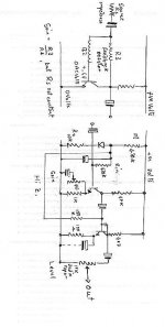
Here is my beta schematic :
there are for the moment 2 stages:
* the first one just amplifie the signal
* the second one use the saturation of the transistor to cut the signal
here is a graphic showing the progress of the signal:
The gain can be changed using R1. I didn't put a tone and volume control yet.
I've tested this schematics and well ... it's a distortion but not what I wanted. Have you got any advice to give to improve the circuit (also about the kind of components ?).
Every critic is welcome.
If I know how to analyse circuits I have never managed to create one on my own.
Here is my beta schematic :
An externally hosted image should be here but it was not working when we last tested it.
there are for the moment 2 stages:
* the first one just amplifie the signal
* the second one use the saturation of the transistor to cut the signal
here is a graphic showing the progress of the signal:
An externally hosted image should be here but it was not working when we last tested it.
An externally hosted image should be here but it was not working when we last tested it.
The gain can be changed using R1. I didn't put a tone and volume control yet.
I've tested this schematics and well ... it's a distortion but not what I wanted. Have you got any advice to give to improve the circuit (also about the kind of components ?).
Every critic is welcome.
An externally hosted image should be here but it was not working when we last tested it.
Hi Mattt,
Your attachments didn't work, yuo might want to try agian. In the mean time check this out.
tonepad -- fx projects
I personally was fond of the sound of the "Tube Sound Fuzz" toward the bottom of the list, also there is a "Fuzz Face" clone if youre into something with more pronounced distortion.
Mike
Here are a few more links. jer
http://www.diyaudio.com/forums/musical-instruments/192119-wannabe-electronics-geek.html#post2630024
http://www.diyaudio.com/forums/musical-instruments/192119-wannabe-electronics-geek.html#post2630024
Sorry for the pictures, here they are:
I wanted to do this kind of stuff for a long time and I've already checked a lot of info on the web and magazines, what I really need now is advices from people who know. All the documents I've read have anwsered but also lift many question.
I've seen your links, thanks") , tonepad seems to be a great way to find schematics, in the same spirit I knew http://www.diyguitarist.com/DIYStompboxes/MyStompboxes.htm
, tonepad seems to be a great way to find schematics, in the same spirit I knew http://www.diyguitarist.com/DIYStompboxes/MyStompboxes.htm
An externally hosted image should be here but it was not working when we last tested it.
An externally hosted image should be here but it was not working when we last tested it.
I wanted to do this kind of stuff for a long time and I've already checked a lot of info on the web and magazines, what I really need now is advices from people who know. All the documents I've read have anwsered but also lift many question.
I've seen your links, thanks
, tonepad seems to be a great way to find schematics, in the same spirit I knew http://www.diyguitarist.com/DIYStompboxes/MyStompboxes.htm
Last edited:
I wouldn't do it that way. Your biassing is totally dependent on the gain of the transistors (wouldn't you at least like to put in some emitter resistors?), which means the clipping is unlikely to be symmetrical, and the input is virtual earth, low impedance, unsuitable as far as I'm concerned for guitar pickups. R13 is doing nothing, and putting a 680Ω resistor in the collector of Q5 (hello, what happened to 2,3 & 4?) means it can drive lowish impedances – not common in guitar circuits – but will flatten batteries in no time.
Mind you, I agree it will distort.
Mind you, I agree it will distort.
I wouldn't do it that way. Your biassing is totally dependent on the gain of the transistors (wouldn't you at least like to put in some emitter resistors?), which means the clipping is unlikely to be symmetrical, and the input is virtual earth, low impedance, unsuitable as far as I'm concerned for guitar pickups. R13 is doing nothing, and putting a 680Ω resistor in the collector of Q5 (hello, what happened to 2,3 & 4?) means it can drive lowish impedances – not common in guitar circuits – but will flatten batteries in no time.
Mind you, I agree it will distort.
Thank you for your feedback. he first transistor is in an common emitter disposition to have an optimal amplification, the input impedance is in fact improve by a 1MOhm resistance from Vin to the ground.
R13, well ... the idea was to put the transistor Q5 in a saturation mode. So I needed to have a low tension between the emitter and collector. But you're right it's useless.
I've try to upgrade the old scheme and that's what have now :
An externally hosted image should be here but it was not working when we last tested it.
An externally hosted image should be here but it was not working when we last tested it.
I tried to fixe the symmetri problem whith D1, I changed the names and get rid of R13. I have strange results . What do you think ?
I've made some upgrades :
I fixed the shity common emitter and the polarisation of the two transistors. Any advices for the transistor and diode ? (I thought to use germanium)
An externally hosted image should be here but it was not working when we last tested it.
An externally hosted image should be here but it was not working when we last tested it.
I fixed the shity common emitter and the polarisation of the two transistors. Any advices for the transistor and diode ? (I thought to use germanium)
Hi Matt,
You might also want to check Geofex "Technology of the Fuzz Face" a very in depth article on the inner workings of the Fuzz Face fuzz, also discussing components etc.
If you want to look beyond the two transistor circuits, there's a lot of discussion on Big Muff circuit variants to be found on the net.
On top of all this there's FuzzCentral, it seems that it's no longer updated, so it could go down anytime, but a wealth of information too, also on things like the Ampeg Scrambler, which is also a very nice fuzzy-esque pedal.
Thank you a lot Jarno ! "Technology of the Fuzz Face" seems to be a real wealth of information , exactly what I needed.
This morning I've improve my scheme again :
As you can see I've fixed the common emitter stage and the polarisation of the two transistors. I will read the info you gave me this afternoon and see what I'm going to change but for the moment I'm quite satisfied .
, exactly what I needed. This morning I've improve my scheme again :
An externally hosted image should be here but it was not working when we last tested it.
An externally hosted image should be here but it was not working when we last tested it.
As you can see I've fixed the common emitter stage and the polarisation of the two transistors. I will read the info you gave me this afternoon and see what I'm going to change but for the moment I'm quite satisfied .
All right, taking your first stage. This is a virtual earth, current feed circuit; to the limit of the transistor's gain, it is going to keep the base at a constant voltage. Its gain is set by the ratio of R3 to the drive impedance.
Unfortunately, the impedance of a guitar pickup is not constant with frequency; an almost pure inductor, it drives more current at low frequencies than high. So this stage will eat all the high frequencies from the instrument (although it might work adequately from a resistive signal generator). And, as the gain of the transistor is high relative to resistor values, it will run very nearly turned full on, the collector barely more than a diode junction above ground, so negative cycles will clip long before positive.
And, with a feedback resistor that small, it's not even particularly high gain.
I suggest a simple high impedance input, biassed straight from the rails, putting the collector at about half way (the capacitor is only to filter out rail noise, probably unnecessary off battery), with an inherently high gain (30+ dBs, or, if you incorporate the emitter bypass capacitor, close to the maximum gain of the transistor. It might be worth incorporating a gain pot, to adjust drive.)
The diode you have added is permanently switched on, sort of a complicated short circuit; remove. If you bias this stage up to half rail, too, it should distort, even if a bit asymetrically; it is another virtual earth circuit with no resistor limiting its input (though the 1k emitter resistor will limit its voltage gain to 20dB; you might consider a bypass capacitor here, too.), and the current the transistor can pump into it is a lot higher than the collector resistor can manage. Still, we're not trying for a minimum distortion circuit. I'd consider a high impedance circuit here, too, or at least a permanent series resistor, but it's less critical. Properly centred that circuit's going to blast out over three volts RMS (with the accent on the "square"), enough to seriously overload most guitar amp inputs, so a "level" pot, as well as the suggested "gain" (or "drive") pot would probably be useful.
I can't get my CAD software to generate any format that this site will accept as an attachment, so I'l just have to scribble it out by hand and scan it in…
Oh, explitive deleted, I'd rotated that…
Unfortunately, the impedance of a guitar pickup is not constant with frequency; an almost pure inductor, it drives more current at low frequencies than high. So this stage will eat all the high frequencies from the instrument (although it might work adequately from a resistive signal generator). And, as the gain of the transistor is high relative to resistor values, it will run very nearly turned full on, the collector barely more than a diode junction above ground, so negative cycles will clip long before positive.
And, with a feedback resistor that small, it's not even particularly high gain.
I suggest a simple high impedance input, biassed straight from the rails, putting the collector at about half way (the capacitor is only to filter out rail noise, probably unnecessary off battery), with an inherently high gain (30+ dBs, or, if you incorporate the emitter bypass capacitor, close to the maximum gain of the transistor. It might be worth incorporating a gain pot, to adjust drive.)
The diode you have added is permanently switched on, sort of a complicated short circuit; remove. If you bias this stage up to half rail, too, it should distort, even if a bit asymetrically; it is another virtual earth circuit with no resistor limiting its input (though the 1k emitter resistor will limit its voltage gain to 20dB; you might consider a bypass capacitor here, too.), and the current the transistor can pump into it is a lot higher than the collector resistor can manage. Still, we're not trying for a minimum distortion circuit
. I'd consider a high impedance circuit here, too, or at least a permanent series resistor, but it's less critical. Properly centred that circuit's going to blast out over three volts RMS (with the accent on the "square"), enough to seriously overload most guitar amp inputs, so a "level" pot, as well as the suggested "gain" (or "drive") pot would probably be useful.I can't get my CAD software to generate any format that this site will accept as an attachment, so I'l just have to scribble it out by hand and scan it in…
Oh, explitive deleted, I'd rotated that…
Attachments
That's the nice thing about guitar pedals, you can get everything from tubescreamer-esque overdrive pedals, to distortions, to fuzzes.
There's even nastier stuff too!
Wrt. the transistors used, I myself really like germanium, most of those are PNP instead of NPN so you'd have to reverse polarity of everything polarised These are known as "positive ground" as the ground is connected to "plus" of the battery, these cannot be used with a daisy chained power supply (with negative ground pedals on the same chain) or you'll short it.
Bought some CV7355's on eBay a while back and they sound great, somewhat more loose than silicon. Tried one with silicon as well, and that sounded buzzier.
Whatever turns your crank
There's even nastier stuff too!
Wrt. the transistors used, I myself really like germanium, most of those are PNP instead of NPN so you'd have to reverse polarity of everything polarised
These are known as "positive ground" as the ground is connected to "plus" of the battery, these cannot be used with a daisy chained power supply (with negative ground pedals on the same chain) or you'll short it.Bought some CV7355's on eBay a while back and they sound great, somewhat more loose than silicon. Tried one with silicon as well, and that sounded buzzier.
Whatever turns your crank
Last edited:
You can easily fit this one into a pedal, it uses subminiature tubes:
http://www.diyaudio.com/forums/tubes-valves/190738-hundred-buck-amp-challenge-51.html#post2632834
http://www.diyaudio.com/forums/tubes-valves/190738-hundred-buck-amp-challenge-51.html#post2632834
Yes, The germanium ones have a softer clipping (saturation) than the silicon ones do.
I used to build mine out of TL07x opamps but I prefered a germanium 1N34 diode to do the clipping.
As I was building my devices, I would look at the scope as well as hear the sound every time I changed a component.
This way I got to know what kind of sound I could expect when I was expeimenting with the amp off.
jer
P.S. I eventualy built an octivizer that sounded like a combo organ or a severly distorted B3 that didn't mistrigger,I sure had alot of fun doing that project and learned a tremendous amount while doing so.
Last edited:
All right, taking your first stage. This is a virtual earth, current feed circuit; to the limit of the transistor's gain, it is going to keep the base at a constant voltage. Its gain is set by the ratio of R3 to the drive impedance.
Unfortunately, the impedance of a guitar pickup is not constant with frequency; an almost pure inductor, it drives more current at low frequencies than high. So this stage will eat all the high frequencies from the instrument (although it might work adequately from a resistive signal generator). And, as the gain of the transistor is high relative to resistor values, it will run very nearly turned full on, the collector barely more than a diode junction above ground, so negative cycles will clip long before positive.
And, with a feedback resistor that small, it's not even particularly high gain.
I suggest a simple high impedance input, biassed straight from the rails, putting the collector at about half way (the capacitor is only to filter out rail noise, probably unnecessary off battery), with an inherently high gain (30+ dBs, or, if you incorporate the emitter bypass capacitor, close to the maximum gain of the transistor. It might be worth incorporating a gain pot, to adjust drive.)
The diode you have added is permanently switched on, sort of a complicated short circuit; remove. If you bias this stage up to half rail, too, it should distort, even if a bit asymetrically; it is another virtual earth circuit with no resistor limiting its input (though the 1k emitter resistor will limit its voltage gain to 20dB; you might consider a bypass capacitor here, too.), and the current the transistor can pump into it is a lot higher than the collector resistor can manage. Still, we're not trying for a minimum distortion circuit
I can't get my CAD software to generate any format that this site will accept as an attachment, so I'l just have to scribble it out by hand and scan it in…
Oh, explitive deleted, I'd rotated that…
Thanks again for your answer and excuse me for answering so late. This is exaclty the level of understanding I'd like to reach.
I now understand the importance of having a high impedance first stage. There are some part of your scheme I still have dificulties to understand but I'm working on it. You all give me lots of information, I will try another upgrade after reading and understanding everything .
A question I have in mind : what are the advantages of using OPAmp that simple transistor ? Whith OPAmps I have the feeling that the bandwidth become an annoying constraint, no ?
I like opamps because to me they are (were) easier for me to understand.
You can also get an incredibly high gain out of them if needed while keeping a very low noise floor.
I am not saying it can't be done with transistors but it just seemed easier with opamps and very straight forward for me.
But learning the transistor circuit design part is a very essenitial thing to learn aswell !
jer
An op amp is easier to design round; no need foe coupling capacitors, near infinite gain, and with modern ones a bandwidth from earthquake frequencies to FM radio transmitter. Gain is set by a couple of resistors, input impedance can be anything you want, power supply rejection is excellent…
If you use a multiple chip you can use a segment for generating a centre rail, one for gain, one distortion and perhaps a tone control.
Against them is the fact that, unless you put external distortion components round them, they're always going to same; and it's not a particularly nice sound. You can't muck around with bias currents and listen to the difference. And, with super high gains there is always the risk of mains buzz on a Fender pickup being amplified to the same level as the instrument playing. Gating the input (doesn't matter if the gate's none too linear, what does a touch more distortion count) can be very useful against this, but adds extra complications; make sure there's space on your board for bodge connections.
And, incidentally, I've never actually built that circuit; it might well sound horrible. Generally, when I want to slug down a waveform I use a linear circuits and add specific distortion components; generally the worst quality diodes I can lay my hands on, yes, germaniums if you can find some, or junctions from a grab-bag of cheap transistors, using diode junctions, of even (once) a CMOS logic hex inverter with feedback round each stage, getting steadily more harmonicky as it went through the circuit.
Generally, you don't want a "Schmitt trigger" type fuzz unless you are going to do something special with the signal afterwards, like triggering a PLL, or playing "keep on running".
I like opamps for Fuzz/Distortion curcuits cuz they are very simple to use, you can get different Distortion characteristics by useing different types and combinations of Clipping diodes ....
Germanium Diodes sound good for that 70"s Rock distortion but they have something like a 0.3v Clipping threshold so they usually need a makeup gain stage after the diode clipping stage .....
Silicon Diodes have a 0.7v clipping threshold so they generally don"t need any makup gain and they have that sort of 80"s metal distortion .....
LED"s have a 1.5v + clipping threshold so in a High gain circuit they are generally a Lot louder than a Silicone or germanium curcuit , I like their sound best , more of a modern metal distortion .......
For the best Overdrive/distortion sound I like Tubes best but they are a lot more finicky than solid state circuits .......
Cheers
- Status
- This old topic is closed. If you want to reopen this topic, contact a moderator using the "Report Post" button.
- Home
- Live Sound
- Instruments and Amps
- Need advice to create my own fuzz