I'm building a clamp to hold drive units for impedance measurements today. The material at hand is mild-steel rectangular tubing.
I'm worried about the magnetic flux in the air gap being affected when the metal tube is in direct contact with the driver magnet assembley. Will this affect impedance measurements of the driver? i.e. do I need to use a non magnetic material to actually clamp the driver?
I'm worried about the magnetic flux in the air gap being affected when the metal tube is in direct contact with the driver magnet assembley. Will this affect impedance measurements of the driver? i.e. do I need to use a non magnetic material to actually clamp the driver?
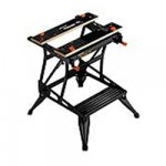
I use a Workmate opened up enough to mount the driver on its back firing upwards. I put a couple of rubber pads between the Workmate and the driver with just 2 small clamps ( one on each side of driver ) to keep it from vibrating, especially during resonance. I always get a nice clean impedance curve using the LMS system.
Works for me
Works for me

Hi Doug,
Since I've got the materials and will probably be doing this a lot, I want to build a dedicated jig for driver measurement. It should have the ability to hold a driver 3' in the air, firing forward , and handle magnet assemblies up to 25cm diameter (my sub magnet is 20cm).
This is my idea:
I've read several references that recommend measuring the driver in its natural position i.e. firing forwards.mount the driver on its back firing upwards
Since I've got the materials and will probably be doing this a lot, I want to build a dedicated jig for driver measurement. It should have the ability to hold a driver 3' in the air, firing forward , and handle magnet assemblies up to 25cm diameter (my sub magnet is 20cm).
This is my idea:
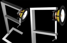
Oh that's just me getting carried away as usual. My approach is to just go OTT and never have to worry about it again.
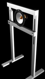
I think I'll settle for this inherently more sturdy design, and i won't have to worry about anything touching the magnet assembly either.
I think I'll settle for this inherently more sturdy design, and i won't have to worry about anything touching the magnet assembly either.
Attachments
Hi. I´m using an engine vise and a large bench vise. Like the one in the link.
http://www.linearx.com/products/software/LEAP5/EnclosureShop/EncShp05.htm
Mid page.
CL
http://www.linearx.com/products/software/LEAP5/EnclosureShop/EncShp05.htm
Mid page.
CL
I've read several references that recommend measuring the driver in its natural position i.e. firing forwards.
Vikash;
I've made the impedance measurements with driver facing upwards and foreward but have not noticed any difference in the impedance plot.
Awesome looking designs you came up with though
Doug
Vikash;
I've made the impedance measurements with driver facing upwards and foreward but have not noticed any difference in the impedance plot.
Awesome looking designs you came up with though
Doug
Yeah it does look nice doesn't it ")
I spent the whole day adjusting SW and measuring one of my drivers and got differing result up to 60 Ohms (90 to 150 at Fs). All measurements were taken with the driver near the floor in different orientations. It was a good illustration to how much reflections affect a driver/sound.
When the clamp is finished, I'll report any differences due to the driver's orientation in mid air.
Vikash;
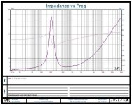
What software are you using? I'm attaching an image of an impedance / phase plot I did recently of a cheap 4 inch speaker that came out of a TV set. I hope I adjusted the pixel width right for this post as I can't preview the attachment before I submit.
What software are you using? I'm attaching an image of an impedance / phase plot I did recently of a cheap 4 inch speaker that came out of a TV set. I hope I adjusted the pixel width right for this post as I can't preview the attachment before I submit.
Attachments
Vikash said:Yeah it does look nice doesn't it
I spent the whole day adjusting SW and measuring one of my drivers and got differing result up to 60 Ohms (90 to 150 at Fs). All measurements were taken with the driver near the floor in different orientations. It was a good illustration to how much reflections affect a driver/sound.
When the clamp is finished, I'll report any differences due to the driver's orientation in mid air.
Vikash;
A difference of 60 ohms seems a bit much. I would check the software you are using for sure. If I get the driver to close to a reflective surface, I notice a slight difference in the impedance plot, but only a couple of ohms here and there at most.
You mentioned that all of your measurements were made near the floor, so if the driver is measured facing upwards, the rear of the driver is close to a reflective surface, but when you orient it so its upright and firing forewards, the reflective surface isn't there, hence the difference in the impedance. But still, a difference of 60 ohms is way to much of a difference.
BTW You didn't mention what software you were using.
Doug
SW = Speaker Workshop. Even though I followed the calibration stages (Eric Wallin's) closely, I was getting acceptable, but not great results. I've narrowed this down to not considering the sound card impedence (default was used).
I used trial and error to calculate a suitable figure and I'm getting better results for impedance measurements now:
DMM, SW, Difference
4.20, 4.20, -0.0
16.10, 16.12 , -0.0
179.20, 178.73, 0.5
467.70, 466.48, 1.2
677.00, 675.51, 1.5
2,689.00, 2,684.00, 5.0
4,695.00, 4,699.00, -4.0
For comparisson, here's the results using default SW impedance for the SC:
DMM, SW, Difference
4.20, 4.20, 0.0
16.10, 16.05, 0.1
179.20, 175.36, 3.8
467.70, 447.06, 20.6
677.00, 636.28, 40.7
2,689.00, 2,180.00, 509.0
4,695.00, 3,357.00, 1,338.0
I guess I should post this on the SW forum, but anyone know an easy way of using Jig II to measure the SC impedance?
Well the bottom line remains. Even with my bad set up, it still measure up to 180 Ohms with acceptable accuracy, so the 60 Ohms fluctuation is still not explained.
Vikash said:SW = Speaker Workshop. Even though I followed the calibration stages (Eric Wallin's) closely, I was getting acceptable, but not great results. I've narrowed this down to not considering the sound card impedence (default was used).
I used trial and error to calculate a suitable figure and I'm getting better results for impedance measurements now:
DMM, SW, Difference
4.20, 4.20, -0.0
16.10, 16.12 , -0.0
179.20, 178.73, 0.5
467.70, 466.48, 1.2
677.00, 675.51, 1.5
2,689.00, 2,684.00, 5.0
4,695.00, 4,699.00, -4.0
For comparisson, here's the results using default SW impedance for the SC:
DMM, SW, Difference
4.20, 4.20, 0.0
16.10, 16.05, 0.1
179.20, 175.36, 3.8
467.70, 447.06, 20.6
677.00, 636.28, 40.7
2,689.00, 2,180.00, 509.0
4,695.00, 3,357.00, 1,338.0
I guess I should post this on the SW forum, but anyone know an easy way of using Jig II to measure the SC impedance?
Well the bottom line remains. Even with my bad set up, it still measure up to 180 Ohms with acceptable accuracy, so the 60 Ohms fluctuation is still not explained.
Hi Vikash,
What sampling freq are you using when measuring? You should only use 11K (or lower if it is available) when measuring a woofer. I initially though the higher the better, but then I found something somewhere in the doco, that said use 11K and the results were much better and consistent. I guess the thing is you don't need the high sampling rate as you don't expect a woofer to need to reproduce freq up to 20Khz (unless you have a full range driver I guess). 11K will still give you up to 5Khz. I can't remember if I did anything with measuring of my sound card's impedance, I think there was an automatic callibration??
BTW, I like the look of your second design better
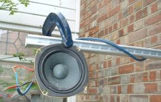
I used a couple of saw horses with the edges of the woofer clamped with G clamps a bit like pink mouse. Just got someone to sit on each saw horse to make sure it was stable I think the biggest concern will be whether you will get resonance in the steel structure itself. I guess its a trade off between being as close an approximation to free air, and being sturdy enough to keep vibrations to a minimum. Regards,
Tony.
Hi Tony,
BTW, the drivers I'm measuring are midbass drivers: Monacor SPH-175
The max my sound card allows: 48Khz.What sampling freq are you using when measuring?
I recall something related to that, although I don't remember the exact reasoning. But at 48Khz, I can measure resisitors up to 4.7 KOhms within 4 Ohms accuracy. Surely that's not a reason to reduce to 11Khz sample rate?I initially though the higher the better, but then I found something somewhere in the doco, that said use 11K and the results were much better and consistent.
Looks more consistent, but doesn't mean more accuracy? Just less sampling stages to hilight differing results?and the results were much better and consistent
There is a test button, the same as with the calibration resistors. But I don't know how to use Jig II to do this. I've read that SC impedance is so high that it will make little effect on the results, but I have found it to the contrary - well at least when considering very high resistor measurements (which have impedances not applicable to transducer measuring anyway)I think there was an automatic callibration??
I thought the same thing. The steel is 2mm thick and hollow, so I will it fill with sand where I can to increase the weight. I was thinking about additionally using weights on the floor beams to hold it steady, but I've already taken it all to a superfluous extreme considering the approach of others....whether you will get resonance in the steel structure itself.
BTW, the drivers I'm measuring are midbass drivers: Monacor SPH-175
Vikash said:Hi Tony,
The max my sound card allows: 48Khz.
I recall something related to that, although I don't remember the exact reasoning. But at 48Khz, I can measure resisitors up to 4.7 KOhms within 4 Ohms accuracy. Surely that's not a reason to reduce to 11Khz sample rate?
Looks more consistent, but doesn't mean more accuracy? Just less sampling stages to hilight differing results?
What I was finding was I could run the measurement three times in a row (edit: on the same speaker) with 48Khz sapmle rate and get wildly different results with spurious peaks in the impeadance curve. When I changed the sampling rate to 11Khz the spurious peaks went away and the results would be the same from test to test. Maybe if you use 48Khz sample rate it also sends the high freq to the woofer, causing problems???
There is a test button, the same as with the calibration resistors. But I don't know how to use Jig II to do this. I've read that SC impedance is so high that it will make little effect on the results, but I have found it to the contrary - well at least when considering very high resistor measurements (which have impedances not applicable to transducer measuring anyway)
I seem to remember something about the accuracy greatly decreasing once you go above a certain resistance, though with impeadance curves, I guess the majority of it is going to be under a few hundred ohms.
I thought the same thing. The steel is 2mm thick and hollow, so I will it fill with sand where I can to increase the weight. I was thinking about additionally using weights on the floor beams to hold it steady, but I've already taken it all to a superfluous extreme considering the approach of others.
Hey I don't think it is extreme. The sand is a great idea, that should make it very solid (although you better pick it's spot well as it may be difficult to move after filling
) The only reason I used a couple of saw horses was that it was all I had. If I had something better I'd use it
BTW, the drivers I'm measuring are midbass drivers: Monacor SPH-175
[/QUOTE][/B]
Well I guess for midbass you would probably want to measure up to maybe 10Khz depending on your crossover freq and slope, So I would try a sampling freq of 20Khz or maybe 16Khz if an impeadance curve up to 8Khz will do. Just give it a try and see how it goes.
Also Have you read the stuff here http://www.gti.net/wallin/audio/audua/audua.html
Note there is now a new jig (I made the original one referenced above)
http://www.gti.net/wallin/audio/SW/SW.html
(edit: just noticed that you mentioned Jig II so you no doubt have read the above).
I got completely crap results before I made the Jig and followed the instructions on calibration.
Regards,
Tony.
found it
Hi Vikash,
found the reference to 11Khz. doesn't really go into any great detail, but here it is.
http://www.speakerworkshop.com/SW/Project/Subwoofer Test A.htm
regards,
Tony.
Hi Vikash,
found the reference to 11Khz. doesn't really go into any great detail, but here it is.
http://www.speakerworkshop.com/SW/Project/Subwoofer Test A.htm
regards,
Tony.
- Status
- This old topic is closed. If you want to reopen this topic, contact a moderator using the "Report Post" button.
- Home
- Loudspeakers
- Multi-Way
- Impedance measurement clamp - URGENT