Hi folks,
I have a Sony STR-6065 receiver that is in great shape except for one major problem: no audio from left channels. Both Main and Remote lefts are not working. When I turn on the receiver, I get an initial "pop" from the left channel speaker, then the right channel gradually comes on as you'd expect from a receiver.
There's 1 fuse and that's not related to the output of either channel. If that was blown, the unit wouldn't even turn on, so I know that's not the issue.
What I've done so far:
1. Checked all connections to speakers and channels
2. Swapped speakers/channels with no change in problem
3. Used Deoxit on all switches and pots.
4. Purchased the service manual and I feel the problem may be traced to the power amplification board. (This is just an assumption and reason why I'm asking for help).
So far, I haven't seen signs of bulging caps. What recommendation do any of you have? This is a real nice looking receiver with decent a decent following and I'd like her to rock again.
Nope... it's in the right section ")
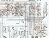
We'd have to see the circuit but most faults like this are caused by a power amp problem... either failed output transistors or a failed "STKxxxx" module if it uses those.
You need to check the DC offset at the L and R amplifier outputs (on the board before any protection relays) as a first step.
We'd have to see the circuit but most faults like this are caused by a power amp problem... either failed output transistors or a failed "STKxxxx" module if it uses those.
You need to check the DC offset at the L and R amplifier outputs (on the board before any protection relays) as a first step.
OK... so with the amp on you have zero volts DC on those 0.5 ohms. I'm surprised tbh, but that's a good result. In a way that means 95% that the problem is elsewhere in the amp... strange
I don't know what test gear you have... a scope and generator would help but I'll assume you haven't access to either.
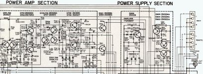
You need to confirm that the six supplies to the faulty channels power amp are correct. Be very careful measuring, one slip will cause a lot of damage.
That's +50volts DC on Q902 and -50 volts DC on Q901.
And confirm the auxilliary supplies of +54 and +55 and - 54 and -55 volts DC from the regulator transistors Q801 and 802. Measure on the collector and emitter of each. These voltages will only be approximate and could be different by 10% or so... we are just confirming they are there.
Make sure these supplies arrive at the power amp as there are some safety resistors along the way.
I don't know what test gear you have... a scope and generator would help but I'll assume you haven't access to either.
You need to confirm that the six supplies to the faulty channels power amp are correct. Be very careful measuring, one slip will cause a lot of damage.
That's +50volts DC on Q902 and -50 volts DC on Q901.
And confirm the auxilliary supplies of +54 and +55 and - 54 and -55 volts DC from the regulator transistors Q801 and 802. Measure on the collector and emitter of each. These voltages will only be approximate and could be different by 10% or so... we are just confirming they are there.
Make sure these supplies arrive at the power amp as there are some safety resistors along the way.
I don't have access to the gear you mentioned but I did check the transistors on the board. Q705's collector is showing 23.6v when it should read 0.8. My initial testing of the other transistors on that board shows numbers that are similar to the service manual's. Nothing as off the charts as Q705.
I will re-read your latest recommendations while I take a break.
I will re-read your latest recommendations while I take a break.
Just very quickly... and its not easy to read the circuit tbh... bit blurry
23 volts on Q705 collector ? Check the Base/Emitter volt drop across Q 708 (the driver) to the "top" output of the output pair. Is it open circuit ? Is the 5.6 ohm OK
Base/emitter going open circuit is a typical failure mode...
All the base emitter volt drops should not exceed around 0.8 volts max.
23 volts on Q705 collector ? Check the Base/Emitter volt drop across Q 708 (the driver) to the "top" output of the output pair. Is it open circuit ? Is the 5.6 ohm OK
Base/emitter going open circuit is a typical failure mode...
All the base emitter volt drops should not exceed around 0.8 volts max.
Just very quickly... and its not easy to read the circuit tbh... bit blurry
23 volts on Q705 collector ? Check the Base/Emitter volt drop across Q 708 (the driver) to the "top" output of the output pair. Is it open circuit ? Is the 5.6 ohm OK
Base/emitter going open circuit is a typical failure mode...
All the base emitter volt drops should not exceed around 0.8 volts max.
Getting 36.1v on Base of Q708. 24.7v on Emitter. 5.6 ohm reads 00.3 to 00.0v. These numbers are WAY out of line !
Q708 is open circuit with 12 volts across its B-E junction.
Edit... maybe try MJE340 as replacement. I can't find any real data on the originals so check package and lead outs before fitting.
Also its good practice to power up initially using a bulb tester (100 watt bulb in series with mains) just in case there is more damage. It can save blown outputs etc.
Edit... maybe try MJE340 as replacement. I can't find any real data on the originals so check package and lead outs before fitting.
Also its good practice to power up initially using a bulb tester (100 watt bulb in series with mains) just in case there is more damage. It can save blown outputs etc.
Last edited:
Carefully check the voltages on Q708 again. Waht are they now ?
There's absolutely no doubt over the original being faulty with those voltage measurements although thats not to say there aren't other problems either caused by or that have caused that failure. Any normal (which covers all in this amp) transistor with more than around 0.8 volts across its B-E when forward biased is faulty.
Was the original transistor the same physical shape as the MJE340 ?
Morning Mooly,
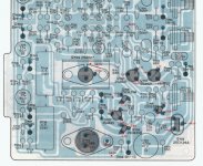
The original transistor was quite different in design. It was a silver, coin shape device with "wings" if you will, for holding two screws. I used the schematic to position the new trannie so the BC and E were identically placed.
I plan on opening her up again today to get some readings.
The original transistor was quite different in design. It was a silver, coin shape device with "wings" if you will, for holding two screws. I used the schematic to position the new trannie so the BC and E were identically placed.
I plan on opening her up again today to get some readings.
Attachments
Last edited:
Hmmm... well I have found a picture of it and it shows as a T03 package. I'm surprised to see that for a driver transistor tbh. The MJE should certainly work though, if only to get prove and get the amp functional.
2sc895 search results
It would help to see how its mounted on the PCB. The case of the 2SC is the collector as is the metal tab of the MJE340.
2sc895 search results
It would help to see how its mounted on the PCB. The case of the 2SC is the collector as is the metal tab of the MJE340.
- Status
- This old topic is closed. If you want to reopen this topic, contact a moderator using the "Report Post" button.
- Home
- Amplifiers
- Solid State
- Sony STR-6065 Receiver Left Channel Issues