Hi everyone, I'm a newbie here @ DIY so please bear with me.
My question is this: I have recently built the 16LS kit from S-5 Electronics and I would like to switch the bridge rectifier chip for the B+ with a rectifier tube (5u4GB maybe?). Has anyone done this or does anyone have a good schematic to do this? Could I use a separate trans. for the 5U4's heater?
My question is this: I have recently built the 16LS kit from S-5 Electronics and I would like to switch the bridge rectifier chip for the B+ with a rectifier tube (5u4GB maybe?). Has anyone done this or does anyone have a good schematic to do this? Could I use a separate trans. for the 5U4's heater?
Well if your amp does use a bridge rectifier then you would need a full wave rectifier tube like the 5u4 plus another set of diodes to complete the bridge. It could be a hybrid bridge of diodes and a tube or even four separate rectifier tubes, like tv damper diodes.
If you could provide a link to the schematic it would make things much easier.
If you could provide a link to the schematic it would make things much easier.
The tube solid state hybrid is sometimes referred to as a Graetz bridge but this actually refers to the four diode topology in general. In this case two of the diodes are solid state and the tube rectifier encompasses the other two..
One potential concern is that tube rectifiers have substantial forward drop compared to soiled state devices resulting in rather lower B+ which in the case of a 5U4 might be as much as 15 - 20V lower (or more) depending on load current. My estimate of drop is based on what I suspect is a fairly modest current draw of a 100mA or so. The 5AR4 might do a little better than this, but at modest currents possibly not.
I am not familiar with the design of this particular amp, but if it uses a CRC based pi-filter the resistor could be replaced with a choke of substantially lower dcr which would help to make up some of the loss.
The other option might just be to get a suitable power transformer, and then still after that a better set of OPTs. You can see where this is heading..
Note that regardless of what you do you will need a filament transformer either 5V or 6.3V depending on the rectifier chosen. I doubt the current filament winding has sufficient capacity (probably an oddball voltage as well) for something like a 6CA4/EZ81 which otherwise could be a good choice.
One potential concern is that tube rectifiers have substantial forward drop compared to soiled state devices
resulting in rather lower B+ which in the case of a 5U4 might be as much as 15 - 20V lower (or more) depending on load current. My estimate of drop is based on what I suspect is a fairly modest current draw of a 100mA or so. The 5AR4 might do a little better than this, but at modest currents possibly not.I am not familiar with the design of this particular amp, but if it uses a CRC based pi-filter the resistor could be replaced with a choke of substantially lower dcr which would help to make up some of the loss.
The other option might just be to get a suitable power transformer, and then still after that a better set of OPTs. You can see where this is heading..
Note that regardless of what you do you will need a filament transformer either 5V or 6.3V depending on the rectifier chosen. I doubt the current filament winding has sufficient capacity (probably an oddball voltage as well) for something like a 6CA4/EZ81 which otherwise could be a good choice.
Last edited:
You get a higher voltage drop across tube rectifiers so ....
This answer is correct with regards to tube rectifier producing lower B+ as others have noted already. Whether you have to make up for it is another question altogether. In many cases the amplifier will work fine if it had more than enough power to satisfy your needs before the mod was made. You can just give it a try, and you may find the 10 to 20+ volt B+ loss may be almost unnoticeable.
To answer your other question, can I use a seperate filament transformer for the 5U4 rectifier, certainly can.
Mickeystan
Hi everyone, I'm a newbie here @ DIY so please bear with me.
My question is this: I have recently built the 16LS kit from S-5 Electronics and I would like to switch the bridge rectifier chip for the B+ with a rectifier tube (5u4GB maybe?). Has anyone done this or does anyone have a good schematic to do this? Could I use a separate trans. for the 5U4's heater?
The other posters have made good points. You will need to buy a filament trafo of some kind, to employ vacuum rectification. Getting rid of the inexpensive (read noisy) SS bridge rectifier makes sense, but staying all SS is (IMO) probably best. 4X 600 PIV Schottky diodes (Mouser part # 726-IDT02S60C) will be just as quiet as vacuum rectification, without the forward drop penalty already mentioned.
Heck, even 4X inexpensive UF4007s will be a distinct improvement.If you are determined to use vacuum rectification, a hybrid bridge will allow the power trafo in situ to continue in service. In vacuum rectifiers, damper diodes have the lowest forward drop. A hybrid bridge setup made from a pair of 600 PIV Schottkys and a 6BY5 dual damper will not be too far off from what's in the unit now.
The suggestion to use a CLC filter, instead of a CRC filter, is excellent. Resistance can be employed in series with the inductor to bring the B+ rail voltage in the same as OEM.
BTW, vacuum diodes can't tolerate large value caps. in the 1st filter position, like SS can.
Re: 16LS Schematic
Thanks Astouffer. Here is the link to the schematic as I built it. BTW, this amp draws about 220ma of current on the B+ measured between the bridge rect. and the 1st filter cap. Current doesn't seem to fluctuate much between idle and full power (5ma max).
http://www.diyaudio.com/forums/tubes-valves/184933-k-16ls-ton-pcb-just-finished-pics-2.html
Actually a better place to determine the amplifier dc current draw is to measure the voltage drop across that 470 ohm resistor in the power supply. (I=E/R) The output of the bridge is ripply dc with a large capacitor charging current and depending on the design of your meter you may or may not get an accurate reading of the amplifier current at this point.
Should the current really prove to be in the vicinity of 220mA the voltage drop across the resistor will be nearly 100V which is more than sufficient margin to allow the use of any tube rectifier you want in conjunction with a smaller resistor or choke. Note that for a 5U4 the input capacitance should probably be kept to 30uF or so, a 5AR4 40uF.. The 6BY5 is one of my favorite damper tube rectifiers but is best used in applications where the dc load current is not too much over 100mA total - so may not be a candidate here.
Last edited:
Hybrid Bridge
I like Eli's post about using 2 schottkys and 1 6by5 for this. Could anyone throw out a schematic for review as I have never built a hybrid bridge with diodes and a tube before.(I just want as much info as I can get before I commit.) If for nothing else this amp uses 2x 5670 tubes that sit in front and 8x 6005 power tubes in the middle of the case and you can't tell me that a nice BIG functional bottle sitting in the back of this tread plated beast wouldn't look really cool.

"Before you can truly appreciate success you must first experience failure."
I like Eli's post about using 2 schottkys and 1 6by5 for this. Could anyone throw out a schematic for review as I have never built a hybrid bridge with diodes and a tube before.(I just want as much info as I can get before I commit.) If for nothing else this amp uses 2x 5670 tubes that sit in front and 8x 6005 power tubes in the middle of the case and you can't tell me that a nice BIG functional bottle sitting in the back of this tread plated beast wouldn't look really cool
.
"Before you can truly appreciate success you must first experience failure."
I like Eli's post about using 2 schottkys and 1 6by5 for this. Could anyone throw out a schematic for review as I have never built a hybrid bridge with diodes and a tube before.(I just want as much info as I can get before I commit.) If for nothing else this amp uses 2x 5670 tubes that sit in front and 8x 6005 power tubes in the middle of the case and you can't tell me that a nice BIG functional bottle sitting in the back of this tread plated beast wouldn't look really cool
"Before you can truly appreciate success you must first experience failure."
Please reread post #8 to understand why the 6BY5 might not in this instance be the right choice for a rectifier tube..
(Noting that I have used this tube for a long time and like it a lot.)
My advice to you would be to change the transformer. Get one that is slightly bigger physically than the one in the kit. There are plenty of makes that are quite reasonable with their prices and one or two may actually be quite helpfull if you tell them want you want to do.Hi everyone, I'm a newbie here @ DIY so please bear with me.
My question is this: I have recently built the 16LS kit from S-5 Electronics and I would like to switch the bridge rectifier chip for the B+ with a rectifier tube (5u4GB maybe?). Has anyone done this or does anyone have a good schematic to do this? Could I use a separate trans. for the 5U4's heater?
Primaries kept the same. Center tapped 6.3volts kept the same. High voltage winding to be changed to two windings of the same voltage each (maybe higher than original) but half the current of the original which will give you a centre tapped secondary to feed to your chosen valve rectifier. Add a second heater winding, the volts and current to suit the heater on your valve rectifier. This is something ANY good transformer manufacturer can do. You may even find something suitable "off the shelf".
Call me crazy but how about this: connect the 2 separate cathodes of a 6by5 together to make a common cathode (basically making an indirectly heated 5u4gb without as much forward voltage drop) and then running 2 in parallel for more current handling capacity to make half of a graetz bridge. The extra filament current is not an issue as I have several filament trafos.
Call me crazy but how about this: connect the 2 separate cathodes of a 6by5 together to make a common cathode (basically making an indirectly heated 5u4gb without as much forward voltage drop) and then running 2 in parallel for more current handling capacity to make half of a graetz bridge. The extra filament current is not an issue as I have several filament trafos.
This should work, but I would probably place a resistor in series with each plate to assure that the load current is shared reasonably well. Something on the order of 47 ohms / 5w ought to suffice.
As far as I can see, the only real advantages of a tube rectifier are:
1. Slow Start
2. ZERO Reverse Voltage Breakdown
3. Authenticity.
There are definite but arguable advantages about SLOW START HT. It is conceivable that COLD cathodes can be stripped if they are not fully warmed up when the B+ is applied to the valves. This is easilly counteracted by fitting a delay in the circuitry that supplies B+.
ZERO Reverse Current, although not completely absent from SS power supplies is not normally an issue. Your HT bridge will be doing its job.
What can never be replicated by SS is true valve authenticity.
It is awkward to replace SS with valves directly. As the previous posts direct, you need separate filament supplies and a higher VAC to achieve the same results.
You can CHEAT - SACRILEDGE I KNOW.
The SS rectifiers plus a slow start HT circuit will do the same job as the tube rectifiers. If you don't want the additional complexity of extra HT transformers and rectifier heaters supplies think about the following CHEAT - and it looks authentic.
Keep the existing SS FWB but add a slow start relay.
Fit a pair of (DEAD) rectifier valves to the chassis for appearance only.
The dead rectifier valves can be illuminated with their own heaters or with LEDs.
SACRILEDGE - MAY I BE CONDEMNED. If you are after authenticity then the problem is ten fold. If you are after appearance - SIMPLE. SS rectifiers are also much more reliable.
Last edited:
Call me crazy but how about this: connect the 2 separate cathodes of a 6by5 together to make a common cathode (basically making an indirectly heated 5u4gb without as much forward voltage drop) and then running 2 in parallel for more current handling capacity to make half of a graetz bridge. The extra filament current is not an issue as I have several filament trafos.
The SS bridge rectifier in situ contains 4 diodes. To make a hybrid bridge, connect the 2 vacuum cathodes together and a plate to each end of the power trafo rectifier winding. Connect the anodes of a pair of SS diodes to ground and a SS cathode to each end of the rectifier winding. You take the "raw" B+ from the junction of the vacuum cathodes.
Vacuum rectifiers can't tolerate large values in the I/P cap. position, along with exhibiting a higher forward voltage drop. Therefore, the entire PSU needs to be reworked. The schematic for the amp shows a cheap simple cap. I/P filter RC decoupled from the small signal circuitry. I hope you have a HEFTY 6.3 VAC filament trafo on hand, as it will have to energize both the signal tube heaters and the 6BY5 heater, The 6.3 VAC winding of the OEM power trafo will be used to boost the voltage the rectifier winding delivers. There are 2 ways to connect that 6.3 VAC winding in series with the primary of the power trafo. One arrangement will raise the rectifier winding's voltage, while the 2nd lowers it. Obviously, you use the arrangement that raises the voltage. The "raw" B+ from the hybrid bridge rectifier feeds a 22 μF. cap., which feeds a 5 H. filter choke, which feeds the existing PSU filter.
BTW, While I appreciate Kevin's concerns about the limitations of the 6BY5, there's little to worry about (IMO). A careful look at the data sheet shows each plate is capable of carrying a continuous 175 mA. current. For a damper type, the 6BY5 has a (sic) low heater to cathode potential limit of 450 V., but it's more than adequate for this particular job.
Cheat?
Andy! Cheat?!? Tsk Tsk! Cheaters never win and winners never cheat. Right now the thermostat in tube heck just got cranked up an extra ten deg. Just for you!!!! I'm just funnin' with ya. I don't mean it...the thermostat is only going up 5 degrees. I did actually consider this but it is waaay to easy and if it is easy when you succeed it just does not taste as sweet. Besides,there is only one thing cooler than tubes...FUNCTIONAL tubes. If you're gonna build a tube amp may as well use all tubes.
Andy! Cheat?!? Tsk Tsk! Cheaters never win and winners never cheat. Right now the thermostat in tube heck just got cranked up an extra ten deg. Just for you!!!! I'm just funnin' with ya. I don't mean it...the thermostat is only going up 5 degrees. I did actually consider this but it is waaay to easy and if it is easy when you succeed it just does not taste as sweet. Besides,there is only one thing cooler than tubes...FUNCTIONAL tubes. If you're gonna build a tube amp may as well use all tubes.
Update
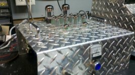
Just an update, I finished the tube rectifier mod on my 16ls kit and it rocks! I ended up using 2 6by5ga tubes in parallel and 2 diodes. After plugging in the tubes I held a nervous finger on the power switch and then said "The hell with it, that's what circuit breakers and fuses are for!" I closed the switch and was amazed by how quiet this amp has become. Befor the mod I could hear some switching noise and a faint hum but they are all gone now. I was able to keep the stock power tranny in service to provide the B+ and heater voltage to the 5670's and 6005's. I added a separate filament tranny to light the 6by5ga's. The increased voltage drop from the tube rectifiers is not at all noticeable, in fact I think this amp has a better and smoother sound quality with a little less B+. I kept the stock crc setup mostly in place but I yanked the 220uf first cap and replaced it with some vintage Aerovox dry electrolytics totalling 30uf and I put 3K ohms in parallel with the 470 ohm resistor to bring the resistance down a bit to compensate for some of the volt drop. I have never heard of anyone doing tube rectification in one of these kits but I highly recommend it. Aside from the obvoius sonic benefits, the two big bottles in the back really look cool!
Just an update, I finished the tube rectifier mod on my 16ls kit and it rocks! I ended up using 2 6by5ga tubes in parallel and 2 diodes. After plugging in the tubes I held a nervous finger on the power switch and then said "The hell with it, that's what circuit breakers and fuses are for!" I closed the switch and was amazed by how quiet this amp has become. Befor the mod I could hear some switching noise and a faint hum but they are all gone now. I was able to keep the stock power tranny in service to provide the B+ and heater voltage to the 5670's and 6005's. I added a separate filament tranny to light the 6by5ga's. The increased voltage drop from the tube rectifiers is not at all noticeable, in fact I think this amp has a better and smoother sound quality with a little less B+. I kept the stock crc setup mostly in place but I yanked the 220uf first cap and replaced it with some vintage Aerovox dry electrolytics totalling 30uf and I put 3K ohms in parallel with the 470 ohm resistor to bring the resistance down a bit to compensate for some of the volt drop. I have never heard of anyone doing tube rectification in one of these kits but I highly recommend it. Aside from the obvoius sonic benefits, the two big bottles in the back really look cool!
Attachments
I did not want to start a new thread just for this, so,
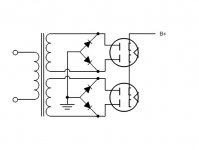
I have a PT with two 300V secondaries and want to use two 6BY5GA in parallel.
Can I connect them like this, or is it better or just as good to parallel the two 300V secondaries and then parallel the 6BY5GAs and use only 2 diodes?
The series limiting resistors are not shown on the drawing.
Thanks.
Scott
Attachments
- Status
- This old topic is closed. If you want to reopen this topic, contact a moderator using the "Report Post" button.
- Home
- Amplifiers
- Tubes / Valves
- Diodes to tube