Hi all
This thread is an offspring from these two posts.
http://www.diyaudio.com/forums/power-supplies/188975-lm317-experiments-measurements-2.html#post2573695
http://www.diyaudio.com/forums/power-supplies/188975-lm317-experiments-measurements-3.html#post2577515
I don’t find appropriate to divert the discussion away from the LM317 there.
I should have responded to Tony a few days back, but I was carried away the last 4 days by many manual–some unnecessary-, semi and fully automatic measurements from two X-Former (self made) implementations of the Symmetric to single ended idea for the oscilloscope “Y Out”.
I have some very small (30mmx25mmx21mm plus 6mm for connection pins) 220Vac/7.5Vac E-I power (core is 12.5x10mm) transformers bought for experimentation.
The first one was built just to see what comes out by unwinding the 7.5Vac secondary (outer winding) and keeping the primary as is. I name this X-former as “Old”
Then, I built a second one, this time with as many secondary turns as the coil window allowed (primary kept again intact). I name this X-former as “New”
After measuring both, it was found that that the two primaries were not identical.
Measuring apparatus used:
Inductance digital meter: Honeytek H623
Capacitance & Inductance digital meter: Mastech MY6243
Function Generator: Hameg HM8030-3
Bench Multimeter Keithley 175 (with 150MHz (X1) probe
Resistanse Decay Box: General Radio 1434-N plus a single 10X10K General Radio Cylinder.
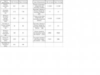
Attached is the result of manual measurements.
I hope to continue tomorrow.
Regards
George
This thread is an offspring from these two posts.
http://www.diyaudio.com/forums/power-supplies/188975-lm317-experiments-measurements-2.html#post2573695
http://www.diyaudio.com/forums/power-supplies/188975-lm317-experiments-measurements-3.html#post2577515
I don’t find appropriate to divert the discussion away from the LM317 there.
I should have responded to Tony a few days back, but I was carried away the last 4 days by many manual–some unnecessary-, semi and fully automatic measurements from two X-Former (self made) implementations of the Symmetric to single ended idea for the oscilloscope “Y Out”.
I have some very small (30mmx25mmx21mm plus 6mm for connection pins) 220Vac/7.5Vac E-I power (core is 12.5x10mm) transformers bought for experimentation.
The first one was built just to see what comes out by unwinding the 7.5Vac secondary (outer winding) and keeping the primary as is. I name this X-former as “Old”
Then, I built a second one, this time with as many secondary turns as the coil window allowed (primary kept again intact). I name this X-former as “New”
After measuring both, it was found that that the two primaries were not identical.
Measuring apparatus used:
Inductance digital meter: Honeytek H623
Capacitance & Inductance digital meter: Mastech MY6243
Function Generator: Hameg HM8030-3
Bench Multimeter Keithley 175 (with 150MHz (X1) probe
Resistanse Decay Box: General Radio 1434-N plus a single 10X10K General Radio Cylinder.
Attached is the result of manual measurements.
I hope to continue tomorrow.
Regards
George
Attachments
Hi George, take as much time as you want, the main thing is that you are enjoying it! Thanks for going to the trouble to do this as well. I'm sure it can be a useful addition to many peoples testing kit, not just mine.
It looks like you have quite a bit of test gear at your disposal!
Tony.
PS. I'm very slow to get things done") The PS prototype I'm taking measurements on I first posted the design for over 12 months ago, and only just got around to building
The PS prototype I'm taking measurements on I first posted the design for over 12 months ago, and only just got around to building
It looks like you have quite a bit of test gear at your disposal!
Tony.
PS. I'm very slow to get things done
The PS prototype I'm taking measurements on I first posted the design for over 12 months ago, and only just got around to building
Last edited:
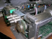
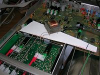
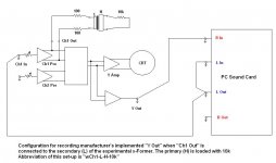
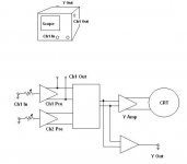
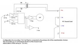
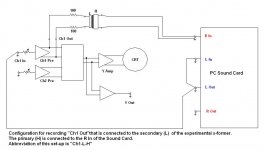
Now, here is one form of “Case 1” implementation of the “diy Y Out”.
This is implemented by using the diy x-former as the “differential to single ended converter” by connecting one coil of the x-former to the output of oscilloscope’s Ch1 Preamplifier Out and the other coil used as the single ended “diy Y Out”.
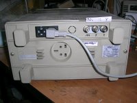
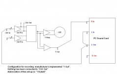
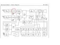
My oscilloscope (Hameg HM203-7) has already a “Y Out” . This, although I installed myself, it was actually per manufacturer’s specs and drawings (the pcb had the tracks ready, only the components were missing). It is not a great lie to say (for the economy of the discussion) that this “Y Out” is “manufacturer’s implementation”.
This is implemented by using the diy x-former as the “differential to single ended converter” by connecting one coil of the x-former to the output of oscilloscope’s Ch1 Preamplifier Out and the other coil used as the single ended “diy Y Out”.
My oscilloscope (Hameg HM203-7) has already a “Y Out” . This, although I installed myself, it was actually per manufacturer’s specs and drawings (the pcb had the tracks ready, only the components were missing). It is not a great lie to say (for the economy of the discussion) that this “Y Out” is “manufacturer’s implementation”.
Attachments
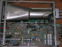
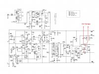
Having this “Y Out”, it is quite convenient to check how this x-former idea performs and if it degrades the performance of the oscilloscope when it is connected to the Ch1 Preamplifier Out.
So I opened up my oscilloscope and started testing.
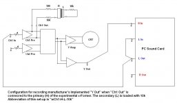
The first set of tests had to test for possible degradation of the oscilloscope performance, when the x-former is connected to the Ch1 Preamplifier Out.
In the attached figures you’ll see what configurations were tested.
So I opened up my oscilloscope and started testing.
The first set of tests had to test for possible degradation of the oscilloscope performance, when the x-former is connected to the Ch1 Preamplifier Out.
In the attached figures you’ll see what configurations were tested.
Attachments
Last edited:
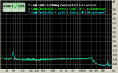

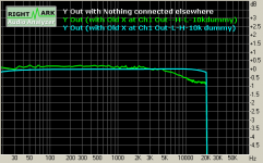
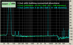
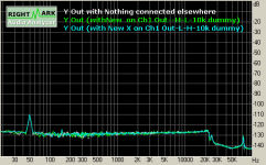
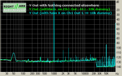
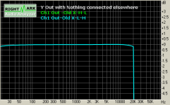
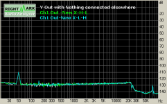
And these are with the "new" x-former.
First att.:frequency response
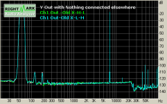
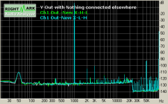
Second att.:Intermodulation distortion (60Hz & 7kHz)
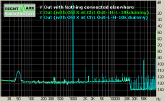
Third att.: Noise
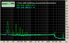
Forth att.: Total harmonic distortion
It is really late. I hope I'll be here tomorrow.
Regards
George
First att.:frequency response
Second att.:Intermodulation distortion (60Hz & 7kHz)
Third att.: Noise
Forth att.: Total harmonic distortion
It is really late. I hope I'll be here tomorrow.
Regards
George
Attachments
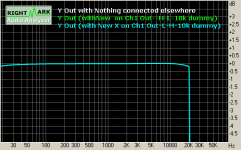
Hmmm big difference with the "new" transformer George, at least on the H - L orientation! It looks like it has minimal impact on the performance.
I'm not 100% clear on what you did with the old and new... old you reduced the number of turns on the secondary, and new you increased the number of turns on the secondary? Looking at how fine the wires are it must have taken a while!!
Tony.
I'm not 100% clear on what you did with the old and new... old you reduced the number of turns on the secondary, and new you increased the number of turns on the secondary? Looking at how fine the wires are it must have taken a while!!
Tony.
Tony, yes the “new” x-former has more turns on the secondary.
It takes time to wind the coils when I have to count the turns or when I have to wind overlapping sections and take out the leads. This was not the case with these two x-formers. It was an easy job.
The “new” x-former seems to perform better. You will notice this on the following measurements.
It takes time to wind the coils when I have to count the turns or when I have to wind overlapping sections and take out the leads. This was not the case with these two x-formers. It was an easy job.
The “new” x-former seems to perform better. You will notice this on the following measurements.
Attachments
Now, the x-formers are used to feed the R In of the soundcard. Their output is compared again to the original “Y Out”.
Edit: My Sound card is an external "M-Audio Audiophile USB"
All recordings here are 16 bit, 192kHz
Edit: My Sound card is an external "M-Audio Audiophile USB"
All recordings here are 16 bit, 192kHz
Attachments

Last edited:
“Old” x-former
First att.:frequency response
Second att.:Intermodulation distortion (60Hz & 7kHz)
Third att.: Noise
Forth att.: Total harmonic distortion
First att.:frequency response
Second att.:Intermodulation distortion (60Hz & 7kHz)
Third att.: Noise
Forth att.: Total harmonic distortion
Attachments

Last edited:
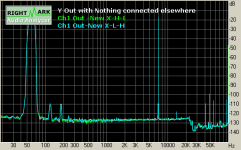
"New" x-former
First att.:frequency response
Second att.:Intermodulation distortion (60Hz & 7kHz)
Third att.: Noise
Forth att.: Total harmonic distortion
First att.:frequency response
Second att.:Intermodulation distortion (60Hz & 7kHz)
Third att.: Noise
Forth att.: Total harmonic distortion
Attachments

Last edited:
Hi George, I saw it along with about 6 others I got that day, some of the others were a bit of a surprise (in a different way to what yours was ) and I've been a bit distracted for a few days I'll return it now, I just completely forgot, I'm terribly sorry about that!
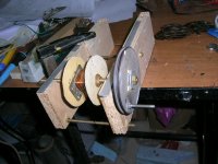
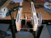
I like the transformer winding jig, simple but functional I've got to get myself some wire and wind some coils for my speakers, I hadn't yet worked out how I was going to do it, but now I at least have an idea
The orientation of the transformer really makes a big difference to the Ch1 out with the old transformer, but with the new one the difference is minimal, does the new one have a 1:1 turns ratio?
Tony.
) and I've been a bit distracted for a few days I'll return it now, I just completely forgot, I'm terribly sorry about that! I like the transformer winding jig, simple but functional
I've got to get myself some wire and wind some coils for my speakers, I hadn't yet worked out how I was going to do it, but now I at least have an idea The orientation of the transformer really makes a big difference to the Ch1 out with the old transformer, but with the new one the difference is minimal, does the new one have a 1:1 turns ratio?
Tony.
Tony, I have no equal when it comes to forgetingI just completely forgot, I'm terribly sorry about that!
No reason to be sorry.I like the transformer winding jig, simple but functional
Thanks. I built it from scratch in an argent need to unwind-measure turns-rewind a burned out radio output transformer. It has provided a lot of service to me since then.
does the new one have a 1:1 turns ratio?
No.
Old is 3.56:1
New is 2.54:1
But I already wound a bifilar 1:1 (same core as the previous two). Measurements are in progress.
Regards
George
As I wrote above, I wound a third x-former using a same core.
This time primary and secondary were wound simultaneously (bifilar).
Turns ratio is 1:1. Each of them consists of 3110 turns on 66 layers.
Winding time 2 hours
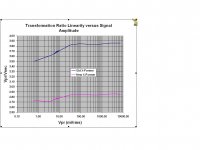
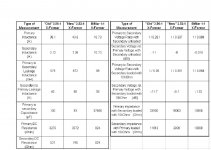
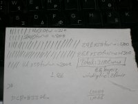
Attached below are the results of manual measurements.
Two encouraging observations.
The –6db HF roll-off is at 250kHz and no resonance up to 2MHz, which is my signal generator’s limit. (This is not shown in the attachments.)
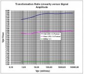
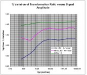
The Vpr/Vsec linearity versus signal amplitude is much better than the previous two x-formers.
Regards
George
This time primary and secondary were wound simultaneously (bifilar).
Turns ratio is 1:1. Each of them consists of 3110 turns on 66 layers.
Winding time 2 hours
Attached below are the results of manual measurements.
Two encouraging observations.
The –6db HF roll-off is at 250kHz and no resonance up to 2MHz, which is my signal generator’s limit. (This is not shown in the attachments.)
The Vpr/Vsec linearity versus signal amplitude is much better than the previous two x-formers.
Regards
George
Attachments
Last edited:
Much more linear! also interesting is the primary to secondary capacitance, MUCH higher, I guess that is due to the bifilar winding the two wires together would be making one very long capacitor
BTW I'm surprised it only took two hours! did you actually count the turns or do you hjave a turn counter as part of your rig?
Tony.
BTW I'm surprised it only took two hours! did you actually count the turns or do you hjave a turn counter as part of your rig?
Tony.
did you actually count the turns or do you have a turn counter as part of your rig?
I count. Every some number of turns I draw a line on a paper. Then I add these lines….
I may upgrade to a higher technology though. Get myself an abacus.
BTW I'm surprised it only took two hours!
It was two hours for winding the x-former. One more hour for winding (transferring) wire from one spool to an other (two feeding spools are required for bifilar winding), half an hour to dismantle the x-former, half an hour to clean the laminations and another half to assemble it again. A few cigarettes -no alcohol, no sex- in between.
Half an hour dipping into shellac and 2 hours baking at 100-120d Celsius. Repetitive sex during baking
A lot of
 afterwards
Regards
George
Attachments
LOL George both at the abacus and at the extra curricular activities
Tony.
Just to make it clear, the “extra curricular” activity during baking time was in lieu of the “rent” for using my wife’s electric oven.
And that was X 3 (three x-formers).
This project has drained me off.
- Status
- This old topic is closed. If you want to reopen this topic, contact a moderator using the "Report Post" button.
- Home
- Design & Build
- Equipment & Tools
- Implementing a “Y Out” on an Oscilloscope