I'm building a 6c33 SET right now. I'm having troubles with the chassis design and i'm considering to make a 2 chassis amp(separate PSU).
Can someone point my in the right direction regarding the design of 2 chassis amps.
What should stay on the PSU chassis(rectifiers, caps, chokes)? How do i ground the chassis.
Can someone point my in the right direction regarding the design of 2 chassis amps.
What should stay on the PSU chassis(rectifiers, caps, chokes)? How do i ground the chassis.
Last edited:
separate PSU
Good morning RVRAZVAN,
i fully support with earlier comments: AC and DC (power supply) separation. All the power supply-components in a single chassis; all the audio-path components in another chassis. Between the 2 chassis a good solid umbillical.
If the distance between that external power supply and the audio-chassis is too big; there is a chance for hummmmmmm because the filaments simply want their supply really close. In that case you can sidestep this problem by placing a capacitor close to the actual component that it must feed. Yes....i know.....then there is no complete seperation of the power supply but you don't want humm anyway. Breadboarding your project will show if you have to do this or not.
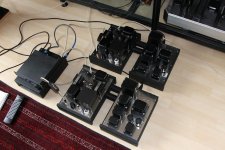
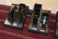
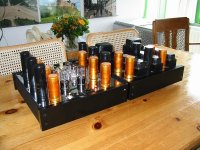
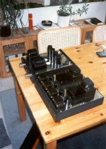
Included some pictures of my EL82 amplifier. Monoblock, 2 chassis each amplifier but with a fixed connection (the tubes between the 2 chassis are hollow; the power lines run through these pipes).
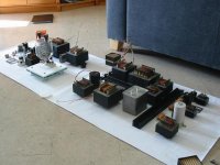
Included some pictures of my big amplifier: the TB3/1000. A completely seperate powersupply with umbillicals. But here the distance became too large hence some capacitors near the audio-components.
In the power supply-chassis: power transformers, rectifiers, capacitors, chokes.
In the audio-chassis: audio-components + final capacitors (DC) for certain components.
Good luck with your project !
Regards, Reinout
Good morning RVRAZVAN,
i fully support with earlier comments: AC and DC (power supply) separation. All the power supply-components in a single chassis; all the audio-path components in another chassis. Between the 2 chassis a good solid umbillical.
If the distance between that external power supply and the audio-chassis is too big; there is a chance for hummmmmmm because the filaments simply want their supply really close. In that case you can sidestep this problem by placing a capacitor close to the actual component that it must feed. Yes....i know.....then there is no complete seperation of the power supply but you don't want humm anyway. Breadboarding your project will show if you have to do this or not.
Included some pictures of my EL82 amplifier. Monoblock, 2 chassis each amplifier but with a fixed connection (the tubes between the 2 chassis are hollow; the power lines run through these pipes).
Included some pictures of my big amplifier: the TB3/1000. A completely seperate powersupply with umbillicals. But here the distance became too large hence some capacitors near the audio-components.
In the power supply-chassis: power transformers, rectifiers, capacitors, chokes.
In the audio-chassis: audio-components + final capacitors (DC) for certain components.
Good luck with your project !
Regards, Reinout
Attachments
Hi
The other alternative would be to make a multi layer case and seperate power supply that way .Pwoer supply transformers at the bottom next level chokes ,next level caps and the top section analog stage's .
With my pre I put them in seperate chassis ,power trannys & chokes in one case analog stage's in the other and the umbillical about 1 meter long .
CHeers
The other alternative would be to make a multi layer case and seperate power supply that way .Pwoer supply transformers at the bottom next level chokes ,next level caps and the top section analog stage's .
An externally hosted image should be here but it was not working when we last tested it.
With my pre I put them in seperate chassis ,power trannys & chokes in one case analog stage's in the other and the umbillical about 1 meter long .
CHeers
WOW. Nice work there( both of you).
My main concern is about the distance between the PSU and the amp. From what i know(might be wrong) the distances must be kept to a minimum between the parts of the psu.
Do i keep any of the filtering caps in the amp chassis or not?
The filaments will be on AC. If i will have the two wires(AC) twisted realy tight an screened i should have no hum issues right?
Also i have a few concerns about grounding an two chassis amp. Hope i won't do anything stupid") .
.
My main concern is about the distance between the PSU and the amp. From what i know(might be wrong) the distances must be kept to a minimum between the parts of the psu.
Do i keep any of the filtering caps in the amp chassis or not?
The filaments will be on AC. If i will have the two wires(AC) twisted realy tight an screened i should have no hum issues right?
Also i have a few concerns about grounding an two chassis amp. Hope i won't do anything stupid
.continue
Good afternoon again RVRAZVAN,
the hum-problems do occur at larger distances. Especially when you use AC at the filaments (are you really sure that you think you can get humm-free 12,6V/3,3A or 6,3V/6,6A). Even if you twist your powerlines very tight.
The only logical solution: breadboarding. So first start with a rough lay-out of all working components and test them in the correct set-up. You will find out IF you have a hum-problem; and at what distances.
When you look at the filament requirements of your tube (6C33), please don't be afraid to use really large diameter wiring.......
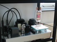
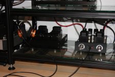
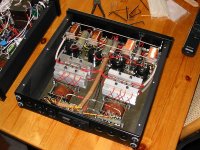
Breadboarding makes sense. It will reveal sensitive parts of your schematic. For instance at my phonostage (all tubes; pictures included) i found out that it was that sensitive that the distance between the external powersupply (with the transformers and there respective magenetic fields) and the actual phonostage had to be quite large. Simply: i could hear the transformer fiels make a hummmmmmmm in the phonostage. Nothing to do with filaments....just magnetics.
So i had serious distances to cover with my powerlines....then AC is not that smart....this will introduce humm also. I switched to DC. And as the distances were quite large i put the final (DC-)capacitor right at the phonostage where it was neeeded.
The same with my headphone-amplifier: again with external power supply. And again at DC with the last (DC-) capacitor at the amplifier itself.
Pictures included of the phonostage and headphonamp (with pictures of the respective power supplies)
Regards, Reinout
Good afternoon again RVRAZVAN,
the hum-problems do occur at larger distances. Especially when you use AC at the filaments (are you really sure that you think you can get humm-free 12,6V/3,3A or 6,3V/6,6A). Even if you twist your powerlines very tight.
The only logical solution: breadboarding. So first start with a rough lay-out of all working components and test them in the correct set-up. You will find out IF you have a hum-problem; and at what distances.
When you look at the filament requirements of your tube (6C33), please don't be afraid to use really large diameter wiring.......
Breadboarding makes sense. It will reveal sensitive parts of your schematic. For instance at my phonostage (all tubes; pictures included) i found out that it was that sensitive that the distance between the external powersupply (with the transformers and there respective magenetic fields) and the actual phonostage had to be quite large. Simply: i could hear the transformer fiels make a hummmmmmmm in the phonostage. Nothing to do with filaments....just magnetics.
So i had serious distances to cover with my powerlines....then AC is not that smart....this will introduce humm also. I switched to DC. And as the distances were quite large i put the final (DC-)capacitor right at the phonostage where it was neeeded.
The same with my headphone-amplifier: again with external power supply. And again at DC with the last (DC-) capacitor at the amplifier itself.
Pictures included of the phonostage and headphonamp (with pictures of the respective power supplies)
Regards, Reinout
Attachments
Good afternoon again RVRAZVAN,
the hum-problems do occur at larger distances. Especially when you use AC at the filaments (are you really sure that you think you can get humm-free 12,6V/3,3A or 6,3V/6,6A). Even if you twist your powerlines very tight.
The only logical solution: breadboarding. So first start with a rough lay-out of all working components and test them in the correct set-up. You will find out IF you have a hum-problem; and at what distances.
When you look at the filament requirements of your tube (6C33), please don't be afraid to use really large diameter wiring.......
Breadboarding makes sense. It will reveal sensitive parts of your schematic. For instance at my phonostage (all tubes; pictures included) i found out that it was that sensitive that the distance between the external powersupply (with the transformers and there respective magenetic fields) and the actual phonostage had to be quite large. Simply: i could hear the transformer fiels make a hummmmmmmm in the phonostage. Nothing to do with filaments....just magnetics.
So i had serious distances to cover with my powerlines....then AC is not that smart....this will introduce humm also. I switched to DC. And as the distances were quite large i put the final (DC-)capacitor right at the phonostage where it was neeeded.
The same with my headphone-amplifier: again with external power supply. And again at DC with the last (DC-) capacitor at the amplifier itself.
Pictures included of the phonostage and headphonamp (with pictures of the respective power supplies)
Regards, Reinout
Your work is amazing
. I have a role model now ).I'm playing with the final tube right now on a breadboard but i still need some big parts to buy or make. I will have an alluminium shassis so that will provide some shielding. Where can i see more of your pictures?
to 6BG6GA
6BG6GA,
thank you for the compliments !
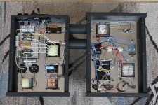
My normal dayjob has a lot to do with radars.....so i want to see some logic in the lay-out of components. I simply get the creeps when i find out an internal chaos in a electronical device.....that will never work; or be prone to failure; or have a short lifespan; etc....
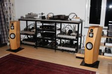
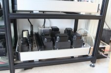
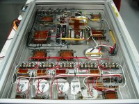
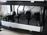
Example: the innards of the external power supply of the big amplifier (TB3/1000). This is quite big and heavy (almost 90 kilo ~ 200 pounds...for each channel). But it is unbelievable stable/constant.
Regards, Reinout
6BG6GA,
thank you for the compliments !
My normal dayjob has a lot to do with radars.....so i want to see some logic in the lay-out of components. I simply get the creeps when i find out an internal chaos in a electronical device.....that will never work; or be prone to failure; or have a short lifespan; etc....
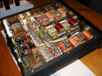
Example: the innards of the external power supply of the big amplifier (TB3/1000). This is quite big and heavy (almost 90 kilo ~ 200 pounds...for each channel). But it is unbelievable stable/constant.
Regards, Reinout
Attachments
I see some Motor run caps around there. Am i right?6BG6GA,
thank you for the compliments !
My normal dayjob has a lot to do with radars.....so i want to see some logic in the lay-out of components. I simply get the creeps when i find out an internal chaos in a electronical device.....that will never work; or be prone to failure; or have a short lifespan; etc....
Example: the innards of the external power supply of the big amplifier (TB3/1000). This is quite big and heavy (almost 90 kilo ~ 200 pounds...for each channel). But it is unbelievable stable/constant.
Regards, Reinout
Can you suggest me where can i use motor caps. I'm was thinking to put some in parallel with the electrolithics in the output tube supply, and in the driver supply to use them all around.
teflon discs
Good evening RVRAZVAN,
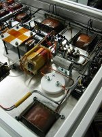
the most "white parts" you'll see in the power supplies are teflon discs. These are used for fixing the capacitors to the chassis. Teflon; great stuff: easy to work with, absolutely safe with high voltage and temperatures.
If i have the change: paper/oil capacitors. But sometimes i simply need polypropylene/oil (motor run) for certain values. Nothing to be ashamed for....nice alternative.
I'm no fan of parallel capacitors.......please chooce a good acapacitor directly instead of trying to improve a mediocre cap with a piggy-back quality one.
Grtz, Reinout
Good evening RVRAZVAN,
the most "white parts" you'll see in the power supplies are teflon discs. These are used for fixing the capacitors to the chassis. Teflon; great stuff: easy to work with, absolutely safe with high voltage and temperatures.
If i have the change: paper/oil capacitors. But sometimes i simply need polypropylene/oil (motor run) for certain values. Nothing to be ashamed for....nice alternative.
I'm no fan of parallel capacitors.......please chooce a good acapacitor directly instead of trying to improve a mediocre cap with a piggy-back quality one.
Grtz, Reinout
Attachments
Hammond H100 organs have the power supply on one chassis, the preamp 6' by wire away, and the power amp 4' away from the preamp. See the service manual on archive.org search H100 Hammond. They use amp commercial mate-n-lock connectors to connect everything, tin plated. No twisted pair or coax between the chassis. Each daughter chassis has a local can electrolytic cap for local B+. Elegant grounding an shielding, no hum, with 15" speakers.
- Status
- This old topic is closed. If you want to reopen this topic, contact a moderator using the "Report Post" button.
- Home
- Amplifiers
- Tubes / Valves
- 2 Chassis amp