Old design - yes I know!
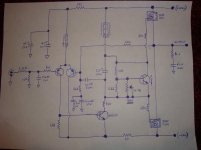
Simulated (LTspice) Nelson's old MF-12 mod to the HK Citation 12. I used andyc's EKV MOSFET models and Bob Cordell's transistor models all included in the .zip file. Just unzip the file in a folder and install the latest LTspice if you don't already have it. See the attached .zip file. I will discuss some of the issues with it here if others are interested in trying the simulation. Might be a good learning tool for Spice. Some of the issues are: Cross conduction during heavy overload
Slight crossover distortion on one edge only - any guesses as to why?
Fairly serious loss of power due to the front end not having higher rail voltages,
clips on the low side at 33-34V peak which is 8-9 volts below the rail.
I had to substitute devices for the models that are available and known to be good. Outputs are IRFP244 the rest you can see in the schematic.
Seems the complementary version is better without making mods to this design, however the IRFP240 has a higher current rating than any of the other devices and it would be nice to take advantage of that and also avoid the odd behavior of the IR P-channel parts.
Attachments
Last edited:
So, complementary version would be better? IRFP9140 and IRFP240 is my choice. After trying different schematics in simulator, I returned to Citation 12, as it is simple, good, and not expensive. Is there any PCB design available for complementary version? Or maybe p2p is way to go with such a low parts count?
So, complementary version would be better? IRFP9140 and IRFP240 is my choice. After trying different schematics in simulator, I returned to Citation 12, as it is simple, good, and not expensive. Is there any PCB design available for complementary version? Or maybe p2p is way to go with such a low parts count?
I've only simulated these and have no experience working on one, or listening to them. I would say yes the fully comp version is better especially if you use a better P type device as you have chosen there - watch out for capacitance some have much more. I simulated the fully comp version here but with a rather weak P ch device, you can put a second one in parallel to see what it will do with a better device - or find models for what you're planning to use:
http://www.diyaudio.com/forums/pass...fully-comp-modification-hk-citation-12-a.html
I don't see any problem with P2P wiring, breadboard etc. but you might search here or on ebay for boards if you really want them.
sorry i know is a bit off topic , can someone please show me how to get this amp working with 2sk134 and 2sj49 ? thk
I'm not familiar with those parts, people have used many different parts in this design so you might start a thread with those part numbers in the title and mention the Pass Citation MOSFET.
I see you were talking about the complimentary design. I have a modified version of the circuit that is being discussed. I am using an IRFP244 and IRFP9240. It sounds pretty darn good in my opinion.
I will atach a "schematic". I am a novice and did not have the original schematic. It is a cross betwenn a schematic and an actual diagram of the PCB going to the connectors on the chasis. If someone could help me get this into LTSpice I would really appreciate it. I have a hard time visualizing how this looks in an actual schematic form. It took me about ten hours just to get the drawing done!
Hi Pete!")
I will atach a "schematic". I am a novice and did not have the original schematic. It is a cross betwenn a schematic and an actual diagram of the PCB going to the connectors on the chasis. If someone could help me get this into LTSpice I would really appreciate it. I have a hard time visualizing how this looks in an actual schematic form. It took me about ten hours just to get the drawing done!
Hi Pete!
Attachments
Hi Mike,
Have you loaded LtSpice on your system and brought in the comp version that I did?
You can then print out the schematic and yours, and mark it up in red taking the values off of your drawing, remember that it will be very close in design so it should not be much work.
Save my original and save yours in a new name. Just get started, look at the RC network across the output, make it match in the real schematic and cross them off of the printout of yours, then move on to the next component - it is not that hard.
In LtSpice just double click on the .asc file to open it, right click on a component to change the value, it is very intuitive to use the cut, wire, move, or copy tools.
If you find it is taking you hours then I'll do it for you.
Are the 1n5305 and 1n5297 two diodes in parallel in your drawing?
You will not be able to run the simulation once you change it since many of the semiconductors are not in the default library but at least you will get a schematic.
Last edited:
I think I did it!!!! I am going to re-write it on paper so it looks nice and legible and I will post a pic. It might not be until tomorrow evening. I will then put it into LTS.
I am amazed at how close it is to the complimentary schematic now that I compare it to my circuit. You said that all along Pete.
This is cool. Progress being made!
EDIT: Sorry Pete, I see you have already put the comp. version in LTS. I will modify that one.
I am amazed at how close it is to the complimentary schematic now that I compare it to my circuit. You said that all along Pete.
This is cool. Progress being made!
EDIT: Sorry Pete, I see you have already put the comp. version in LTS. I will modify that one.
Last edited:
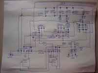
Here is my finished schematic!! The two unmarked transistors are a dual six lead "custom" transistor. I have no idea what it is. I believe it is mentioned in the PASS DIY article. It is SO much easier to see how my circuit works with a good schematic!!
Pete, could you please explain why the current regulating diodes are used instead of the resistors? Could you also explain what the C1 bootstrapping cap was used for and why it is not present in my circuit?
My current power supply filter caps are 17000uf 50v each. The original schematic calls for 6000uf 50v caps. Are 17000uf caps necessary, and if not, what is the lowest uf I could use without hurting the performance of the amp? I was thinking about replacing these as I am sure they must be over twenty years old.
Attachments
That's what I came up with too. My only question is the 1.62 resistor (R15), is that supposed to be 1.62K? With 1.62 Ohms the adjust pot is pretty much useless. I too wonder about the lack of the bootstrap capacitor, maybe it's not needed with CCS diode. If you want to change your CCS diode symbol it's just like a normal diode symbol but with a circle instead of a triangle, the circle on top, line on the bottom in this case.
Craig
Craig
Thanks! Let me double check on the resistor, but you are probably right. The BIAS pot definitely does something because I learned what happens if you try to BIAS it too much! I poofed both the 2N5551's! I will change the symbol too. I am going to work on putting the schematic in Spice tonight after my son is in bed.
Do you have any suggestions on transistors if I ever have to replace the "custom" dual transistor? Thanks again!
I poofed both the 2N5551's! I will change the symbol too. I am going to work on putting the schematic in Spice tonight after my son is in bed.Do you have any suggestions on transistors if I ever have to replace the "custom" dual transistor? Thanks again!
I think the original used the custom dual or a pair 2N5087s. Nelson used MPSL51s for the input diff. and MPSL01s for the VAS and bias. Those are still available at surplus places as I ordered a bunch for my PASS A40 project. I imagine there are several other devices still being manufactured that would be suitable though I've never looked for any. Did you find any info on those CCS diodes. Mouser has some in stock, just Google the part numbers and see what turns up. I used them in my A40 instead of the FETs and resistors.
Craig
Craig
I will check out the 51's and 01's. Is there any point to replacing the custom dual and the two 2N5551's? I found info. for both of the CCS's at mouser. You can still get the 1N5297's. I never had any luck finding the 1N5305's in stock anywhere. That is OK because they are currently (pun intended) fine. Sorry, that was bad, but I couldn't resist. Dang, I did it again.
You are correct the resistor is 1.62K. I am going to start working on the schematic in Spice.
Mike
You are correct the resistor is 1.62K. I am going to start working on the schematic in Spice.
Mike
No reason to change unless there's a problem with reliability such as adjusting the bias you wiped out the 2N5551s. Maybe a tougher xsistor would not do that. Have you checked out all of the Citation 12 articles on the PASSDIY website? I know he did some updates to cover parts no longer available, not sure about the MF12 though.
Craig
Craig
Pete, could you please explain why the current regulating diodes are used instead of the resistors? Could you also explain what the C1 bootstrapping cap was used for and why it is not present in my circuit?
My current power supply filter caps are 17000uf 50v each. The original schematic calls for 6000uf 50v caps. Are 17000uf caps necessary, and if not, what is the lowest uf I could use without hurting the performance of the amp? I was thinking about replacing these as I am sure they must be over twenty years old.
Consider that if you have a constant voltage across a resistor, then the current is constant since: I = V/R and we want a constant current source in the "tail" end of the diff pair. If the transistors are matched and the Vbe's are the same then the current will divide evenly between the pair. The bases should be close to ground, and the emitters are at the same voltage since they are tied together. The emitters are just a diode forward drop below the base so nearly all of the rail voltage is across the tail resistor and since the base signal is small the current variation in the tail is small even with a resistor. However, consider that the main supply is not a perfect voltage source and is modulated by mainly the current drawn by the output stage. We can consider this modulation as a noise source on the rail and it will tend to modulate the current in the diff pair tail. What the diode does is to regulate and nearly keep the current constant, and in so doing reject the noise on the rail.
The bootstrap cap combined with the resistors forms a fairly good constant current source. Remember that the output stage is roughly unity gain so the output voltage is equal to the VAS voltage, the bootstrap cap is large so the voltage on it does not change much at audio frequencies holding a constant voltage on the lower resistor and therefore current to the VAS. The VAS is the main voltage gain stage of the amp, and the gain for this stage goes up as you increase the load impedance, a current source by definition has an infinite impedance so it provides the most gain. This boosts the open loop gain of the amp so that there is more feedback gain to correct for errors in the output providing lower closed loop distortion. The bootstrap cap is far from an ideal current source and the diodes just do a better job. Constant current sources can also be made with transistors, and FETs, just google them for more info.
- Status
- This old topic is closed. If you want to reopen this topic, contact a moderator using the "Report Post" button.
- Home
- Amplifiers
- Pass Labs
- Simulation - Pass MF-12 MOSFET Quasi Comp (Original) Modification for HK Citation 12