I have only a small knowledge of electronics and initially I am trying to get to understand PSU Designer II. I need to come up with a different power supply for a RH84 SE amp build because my main transformer is a little low powered. ( RH 84 - Tube Audio ...... RH DESIGN )
Secondary 1. 325-0-325v at 100 mA
Secondary 2. 6.3v at 3A
Secondary 3. 5 or 6.3v at 2A
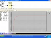
I hoped to use a 5Y3 rectifier but continually came up against the ‘forward current has been exceeded’ (0.44A) warning message. Substituting a 5V4G has improved things, see below. The target is 300v so the B+ is still a little high. I will add the 0.47uF by-pass capacitor and a bleed resistor but I expect to still have to add additional resistance to get the voltage down.
The figures for the transformers have been measured but the choke figures come from a Hammond data sheet.
Am I on the right track or should I add additional filters to improve things?
Any advice would be appreciated.
Graham
Secondary 1. 325-0-325v at 100 mA
Secondary 2. 6.3v at 3A
Secondary 3. 5 or 6.3v at 2A
I hoped to use a 5Y3 rectifier but continually came up against the ‘forward current has been exceeded’ (0.44A) warning message. Substituting a 5V4G has improved things, see below. The target is 300v so the B+ is still a little high. I will add the 0.47uF by-pass capacitor and a bleed resistor but I expect to still have to add additional resistance to get the voltage down.
The figures for the transformers have been measured but the choke figures come from a Hammond data sheet.
Am I on the right track or should I add additional filters to improve things?
Any advice would be appreciated.
Graham
Attachments
firstly, to properly model your transformer you need to either measure or look up the winding resistance and use the source impedance calculator to get an appropriate value plugged in for it. did you do that already?
secondly, how much current you looking to get out of it? is 100ma a placeholder for maximum transformer current? due to misc losses its going to be slightly higher then 100mA on the transformer windings if you have a 100mA load
secondly, how much current you looking to get out of it? is 100ma a placeholder for maximum transformer current? due to misc losses its going to be slightly higher then 100mA on the transformer windings if you have a 100mA load
Last edited:
Hi ryuji,
Thanks for your response.
I measured the transformer and used the impedance calculator.
The load of 100 mA was obtained by adding the requirements for both EL84's and the ECC81 (about 2x48 + 3 mA).
My concern is that this is already at the max for the transformer?
Graham
Thanks for your response.
I measured the transformer and used the impedance calculator.
The load of 100 mA was obtained by adding the requirements for both EL84's and the ECC81 (about 2x48 + 3 mA).
My concern is that this is already at the max for the transformer?
Graham
Your likely running past the limit of your transformer. Set the simulation recording delay to 1 second run sim and then scroll to the right to find rms current requirment of transformer, I bet it will be significantly overloaded. If your buying a new transformer, try out in your sim a 400v transformer and no input cap, just direct connection to inductor, you should get really close to 300v out and the inductor input will reduce rectifier current surges
I'm also building this circuit and trying to figure out my power supply, though I'm not using simulation software. It has a 47uF cap before the choke and 220uF after that. I understand that the 220uF value is not critical and can be increased, but that increasing the 47uF to, say, 100uF will have a damaging effect on the choke or the power transformer? I don't quite understand why since both are 'smoothing' the waveform of the DC, right?
Hi ryuji,
I hope I have carried out your instructions properly.
Running the one second delay I get 117.3 mA at the transformer and 100.22 mA at the load.
What is also confusing me is that I have previously read on this forum that others have successfully used the same transformer for the RH84?
Hi Carbondated,
From my limited knowledge, I have established that the value of the first cap can significantly change the B+ value.
Lower cap, lower B+.
Higher cap, higher B+.
I am not conversant with this damaging the choke.
Graham
You get diminishing returns on higher cap values before choke. Only way to hurt a choke to my knowledge is to overheat it by pulling too much continuous current through it
Rms voltage is 1.4142 times the transformer secondary voltage, subtract the rectifier droop from that value and that gets you your ' ideal' voltage out
Larger input cap means less ripple and in its place more dc
it could be ok to slightly overload that transformer -- perhaps its conservatively rated
The load of 100 mA was obtained by adding the requirements for both EL84's and the ECC81 (about 2x48 + 3 mA).
I run my EL84's at 38ma not 48ma. That should take some of the strain off of your transformer.
")
Last edited:
So I will need to modify the schematic to achieve this.
Hi Graham,
Maybe not, I would build it as is. The 270 ohm resistor chosen by Mr Kittic sets the cathode bias voltage which you can measure. From that you can derive the current flowing through it from Ohm's law. This will give you a rough idea of anode current.
HTH Bill
Last edited:
Morning Bill,
I really enjoy my 'Darling' amp which is currently paired with Frugal Horn Mk 3 full range speakers. They suit the music I like to listen to.
I'm hoping that the RH84 will give me just a little more power to play with.
Thanks once again for your help as I now have a clearer understanding of where I am heading.
Regards,
Graham
Thanks for your help.
Perhaps someone using a similar transformer will post on the forum.
I did. It was a vintage, NIB Stancor PTX with three secondaries: 650Vct @ 150mA; 6.3V @ 5A; 5V @ 3A. I needed a 350Vdc rail. It overvolted badly with Si diodes, some 450Vdc. The choice was either to use the voltage reducer from MOSFET Follies (essentially a current boosted Zener diode) or look into something else. Since the secondary was rated at 5V and 3A, that suggested something like a 5U4GB or the 5BC3 (essentially a 5U4GB with a higher PRV, and a Novar base, otherwise a plate characteristic quite like that of the 5U4GB) Well, I have a bunch of 5U4GBs, and Octal sockets, but no Novar's, and I didn't need the extra PRV for this, so I went with the 5U4GB, a 34uF reservoir capacitor (two 68uF / 300V units in series) followed by a 2nd order LPF with 7H and 220uF. Measured 352Vdc, so it was obvious that this Stancor had been intended for use with the 5U4GB to produce 350Vdc.
Secondary 1. 325-0-325v at 100 mA
Secondary 2. 6.3v at 3A
Secondary 3. 5 or 6.3v at 2A
If that's a 5V @ 2A secondary, then it wants a 5Y3. If that still overvolts, then see the MOSFET Follies site for a solution to get the output down to the 300Vdc you want. Either that, or try to trade that PTX for one more suited to what you're after.
Hi Miles,
Thanks for the information.
The problem I was up against with the 5Y3 was that the 'forward current is being exceeded' message kept appearing. Upon changing to the 5V4G, which also has a 2v heater, I managed to get away from the warning and now I am left with knocking down a few excess volts, which should not be difficult to achieve.
I would have preferred to use the 5Y3 as it is physically a little more compatible with the other valves. Can't win 'em all.
I will checkout Mosfet Follies.
Graham
- Status
- This old topic is closed. If you want to reopen this topic, contact a moderator using the "Report Post" button.
- Home
- Amplifiers
- Tubes / Valves
- RH84 Power supply