Hi all,
First off let me say sorry if this thread should be in another section and that I have done some research but to no avail.
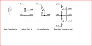
Basically I am looking at modifying a cheap headphone amp I have and so I am drawing a schematic for it to have as a reference. The problem I have come across is how the volume pots are connected. Going by this http://sound.westhost.com/pots-f6.gif pin one of each resistor should be connected. But when continuity tested there is a connection between pins 1 and 2 of resistor 1 and a seperate connection between pins 1 and 2 of resistor 2.
Could some help me to understand why this is done or atleast lead me in the direction of some reading? Ifyou need anymoreinfo please ask and thanks for your time.
First off let me say sorry if this thread should be in another section and that I have done some research but to no avail.
Basically I am looking at modifying a cheap headphone amp I have and so I am drawing a schematic for it to have as a reference. The problem I have come across is how the volume pots are connected. Going by this http://sound.westhost.com/pots-f6.gif pin one of each resistor should be connected. But when continuity tested there is a connection between pins 1 and 2 of resistor 1 and a seperate connection between pins 1 and 2 of resistor 2.
Could some help me to understand why this is done or atleast lead me in the direction of some reading? Ifyou need anymoreinfo please ask and thanks for your time.
I don"t really understand your question as I don"t see any resistors just Pots .....
All the Pins of a pot are connected internally ...... Therefor you will get continuity no matter what 2 pins of the pot your are testing ......
In a dual pot that is wired as a dual volume controll you will get continuity between all the pins of both pots because both pots have a common ground connection and are therfor connected together .....
I don"t know if that is the answer you are looking for , if it isn"t maybe elaborate a bit more on what you want to know ....
Cheers
Measuring with a continuity meter you shouldn't see continuity (v.low resistance) between the 3 pins of a pot, if the wiper is set to the mid position.. If, OTOH, the wiper is set to the end of its travel, then the resistance between it (the middle pin) and one of the other pins will be v. low.
w
w
The pot is a single resistor. Think of something like a pencil lead that is a little bit conductive.
In the diagrams (and those numbers are pin numbers not resistors) pin 1 would be one end of the lead, and pin 3 the other. Pin 2 is a sliding connection that moves from one end to the other or what we call the wiper.
If you got pins 1 and 3 reversed the pot would work "back to front"
In the diagrams (and those numbers are pin numbers not resistors) pin 1 would be one end of the lead, and pin 3 the other. Pin 2 is a sliding connection that moves from one end to the other or what we call the wiper.
If you got pins 1 and 3 reversed the pot would work "back to front"
- Status
- This old topic is closed. If you want to reopen this topic, contact a moderator using the "Report Post" button.
- Home
- Design & Build
- Parts
- Potentiometer Connection Help