Hello Y’all !
Last couple of weeks I spend my time working on a new power amp, or actually two mono blocks.
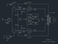
Being a great fan of the SE amplifiers designed by Alex Kitic and their use of Shade feedback,
I used the schematic of the RH84SE as the basic starting point.
Being said “a push-pull amplifier is basically two single ended amplifiers with a phase splitter”,
and inspired by SY’s experiments in this thread , I decided to give it a go.
In the thread mentioned, I read that the load on both sides of the LTP should match as much as possible,
as any variation in the load effects the balancing act of the LTP. There I remembered Shoog’s scheme of using a
bypassed CCS in each cathode of a PushPull output stage, tying the negative sides of the bypass caps together and
referencing the node created to ground with a 1meg resistor. Fortunately, Shoog responded very helpful to a PM I send
him, and he gave me the full low down on this scheme. Thanks again, Shoog !
Having never had any experience with current sources (or sinks, as that’s basically what they are in here), I thought
“K.I.S.S.” and went for the most basic form of a CCS, the LM317 with a resistor.
I made them variable with a trimpot, so now I’m able to dial out the imbalance, measuring the voltage at the two anodes of the ECC81.
In practice, I used one fixed resistor setting the current of the EL84 to 40mA, and used a trimpot on the other CCS to balance things out.
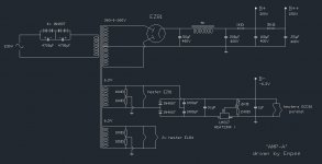
For the LTP, the CCS needs a couple of volts to work properly. I made a negative supply from a spare heater winding followed by
a voltage doubler, and used another LM317. As this LM317 is used as a voltage regulator, it needs some current to function well.
In the end, I set the negative voltage to 6,3 volts and used it to heat the ECC81.
The power transformers were a bit too high in voltage, so I had to dump about 80volts of DC. That’s why there is a
1K resistor in the PSU. I used a 50W resistor in a TO-220 package which shares a heatsink with the LM317 for the negative supply.
Needless to say, this amp became the quietest amplifier I ever build. Even on my ~100dB/w speakers, there is not a hiss nor
hum to be heard.
Just after the powerswitch, there is a DC blocker as I have had trouble with DC offset on my wall outlet, resulting in a very
hot power transformer. Using this DC blocker , the power transformer runs nice and cold.
I had some very nice output transformers lying around with 43% UL taps, so I figured to use them as well.
So there you have it;
A CCS’ed LTP, followed by a fully differential output stage, using shade feedback AND ultra linear connection.
The amp has been playing for a few hours now so it’s kind of early to say it’s perfect, but I really like the sound of it so far.
The bass is really tight and well damped, but that might just be my impression having listened to single ended amps for the last 3 years.
I would like to thank all of the regular posters on DIYaudio.com for their inspiration and meaningful comments.
Cheers,
Empee
pronounced “Amp-A”
Last couple of weeks I spend my time working on a new power amp, or actually two mono blocks.
Being a great fan of the SE amplifiers designed by Alex Kitic and their use of Shade feedback,
I used the schematic of the RH84SE as the basic starting point.
Being said “a push-pull amplifier is basically two single ended amplifiers with a phase splitter”,
and inspired by SY’s experiments in this thread , I decided to give it a go.
In the thread mentioned, I read that the load on both sides of the LTP should match as much as possible,
as any variation in the load effects the balancing act of the LTP. There I remembered Shoog’s scheme of using a
bypassed CCS in each cathode of a PushPull output stage, tying the negative sides of the bypass caps together and
referencing the node created to ground with a 1meg resistor. Fortunately, Shoog responded very helpful to a PM I send
him, and he gave me the full low down on this scheme. Thanks again, Shoog !
Having never had any experience with current sources (or sinks, as that’s basically what they are in here), I thought
“K.I.S.S.” and went for the most basic form of a CCS, the LM317 with a resistor.
I made them variable with a trimpot, so now I’m able to dial out the imbalance, measuring the voltage at the two anodes of the ECC81.
In practice, I used one fixed resistor setting the current of the EL84 to 40mA, and used a trimpot on the other CCS to balance things out.
For the LTP, the CCS needs a couple of volts to work properly. I made a negative supply from a spare heater winding followed by
a voltage doubler, and used another LM317. As this LM317 is used as a voltage regulator, it needs some current to function well.
In the end, I set the negative voltage to 6,3 volts and used it to heat the ECC81.
The power transformers were a bit too high in voltage, so I had to dump about 80volts of DC. That’s why there is a
1K resistor in the PSU. I used a 50W resistor in a TO-220 package which shares a heatsink with the LM317 for the negative supply.
Needless to say, this amp became the quietest amplifier I ever build. Even on my ~100dB/w speakers, there is not a hiss nor
hum to be heard.
Just after the powerswitch, there is a DC blocker as I have had trouble with DC offset on my wall outlet, resulting in a very
hot power transformer. Using this DC blocker , the power transformer runs nice and cold.
I had some very nice output transformers lying around with 43% UL taps, so I figured to use them as well.
So there you have it;
A CCS’ed LTP, followed by a fully differential output stage, using shade feedback AND ultra linear connection.
The amp has been playing for a few hours now so it’s kind of early to say it’s perfect, but I really like the sound of it so far.
The bass is really tight and well damped, but that might just be my impression having listened to single ended amps for the last 3 years.
I would like to thank all of the regular posters on DIYaudio.com for their inspiration and meaningful comments.
Cheers,
Empee
pronounced “Amp-A”
Attachments
I am sure your amp sounds OK, so I am sure you enjoy it.
Unfortunately a triode driver isn´t the most suitable for Schade, something that has been vividly discussed here. This as one get unessecarily high distortion.
If you use a depletion MOSFET, pentode or a ECC81 cascode, things will be really good. Still your present amp will have OK distortion due to PP. Check the works, of among others, Rod C., MJK and Shoog at this forum.
Maybe you can adjust it in your next amp. Don´t take this as criticism just a friendly recommendation for even better performance.
.Unfortunately a triode driver isn´t the most suitable for Schade, something that has been vividly discussed here. This as one get unessecarily high distortion.
If you use a depletion MOSFET, pentode or a ECC81 cascode, things will be really good. Still your present amp will have OK distortion due to PP. Check the works, of among others, Rod C., MJK and Shoog at this forum.
Maybe you can adjust it in your next amp. Don´t take this as criticism just a friendly recommendation for even better performance.
Last edited:
Very nice Empee
Being both a fan of Alex's Rh84se and Gingertubes Babyhuey I think I might give this one a go just to hear what it sounds like. I have most of the parts already in my stash box including Mullard ECC81's, LM317t's and even a pair of hammond 1609 output transformers (Raa = 10k).
Brgds Bill
Being both a fan of Alex's Rh84se and Gingertubes Babyhuey I think I might give this one a go just to hear what it sounds like. I have most of the parts already in my stash box including Mullard ECC81's, LM317t's and even a pair of hammond 1609 output transformers (Raa = 10k).
Brgds Bill
Last edited:
Hi !
Thank you very much for your comments !
@ Zen Mod;
I see the drawing (t)error now. the trimpot on the LTP CCS should be in
the other lead to ground. I will re-draw this as soon as I find the time.
all wires (lines) crossing are connected, when it's not I draw a half-circle
on the crossing
....I'm drawing everyting in ACAD you know....
@ revintage:
Yes, I am aware of the triode being sub-obtimal for driving the Shade feedback,
but as said; this was an experiment and it works very well.
And yes, there's room for improvement
@ Soonerorlater;
Yes, the powersupply as drawn is for one channel only.
Best to design a new PSU for your amp using PSUD !
Cheers !
@ Soonerorlater;
Yes, the powersupply as drawn is for one channel only.
Best to design a new PSU for your amp using PSUD !
Think I'll use the power supply from my babyhuey - it's around 310v dc for the B+ and is good for at least 200ma.
Matching up my cd source might require a bit of experimenting though.
LM317 can be 1/2 cross referenced for tighter matching, search Blumlein's Garter.
A zenier diode in parallel with each CCS necessary if exploring beyond class A.
Cathode resistors added above CCS in LTP might slightly increase effective plate
resistance? I agree triode here not the best choice to emulate a triode overall.
A zenier diode in parallel with each CCS necessary if exploring beyond class A.
Cathode resistors added above CCS in LTP might slightly increase effective plate
resistance? I agree triode here not the best choice to emulate a triode overall.
Last edited:

The main snag I can see is that the LTP has a low anode load due to the anode follower feedback around the output stage (sometimes known as Schade). This will cause distortion in the LTP, mainly odd-order.
For AC purposes the outputs do share the CCS. For DC they are separate. This should maintain balance, while avoiding the usual problem (poor dynamic bias) of CCS bias for an output stage.
For AC purposes the outputs do share the CCS. For DC they are separate. This should maintain balance, while avoiding the usual problem (poor dynamic bias) of CCS bias for an output stage.
What makes it the quietest amplifier you've ever built?Needless to say, this amp became the quietest amplifier I ever build. Even on my ~100dB/w speakers, there is not a hiss nor
hum to be heard.
What makes it the quietest amplifier you've ever built?
lack of noise perhaps ;-)
Niiiiiiiice onelack of noise perhaps ;-)
I'm still building the quietest amp ever. Once its finished, I hope to have fixed that.
Back to Triode driven Schade for a sec: Low plate Z not automatically a problem,
just so the driving plate Z is more or less a constant value. Even if we use high Z
device, cascode or whatever, another problem remains. Conversion of voltage to
current is not linear unless corrected by cathode feedback. Still needs unbypassed
linear resistor under cathode or source. I don't think looking into another Triode's
cathode (folded by CCS tail) provides the required resistance linearity. Needs to
be some actual resistance there to nail down the variable Gm.
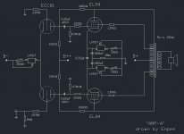
Just to point out, you have done a serious(but easy to fix) mistake trying to mate two RH84s as PP:
Though triodes aren´t the best suitable for the task the 250ohm unbypassed cathode resistors are essential to get an acceptable function. Otherwise even worse distortion will be at hand.
Ad them from each cathode to the junction of the CCS.
Not hard to correct, will only take a few minutes...
) mistake trying to mate two RH84s as PP:Though triodes aren´t the best suitable for the task the 250ohm unbypassed cathode resistors are essential to get an acceptable function. Otherwise even worse distortion will be at hand.
Ad them from each cathode to the junction of the CCS.
Not hard to correct, will only take a few minutes...
Last edited:
Hey!!!! Yours as well? That is an amazing coincidence. Ah man...the background noise is a velvety pitchblack when I've turned my Baby Huey off.You should hear it when it's turned off !!
You should hear it when it's turned off !!
When I turn my Babyhuey off all I hear is my tinnitus.........

Read somewhere that pycnogenol may help for tinnitus.tinnitus.
- Status
- This old topic is closed. If you want to reopen this topic, contact a moderator using the "Report Post" button.
- Home
- Amplifiers
- Tubes / Valves
- Amp-A, a variation to the EL84 Push Pull theme