Hello, I'm currently building a psu from recycled components ( except for electrolytic caps- been there, done that, never again ! ) and I'm trying to tweak the best out of an LM317 and LM337 pair. Noise being an issue with these 3 term regs I found a reference in a post "Squeezebox power supply " august 2006 .
[special=
Better yet, if you can replace R2 with somethig like a zener diode*, you'll get lower noise all the way down to DC - because the dynamic impedance of the zener will much lower than the required value of R2 (just 1-5ohms insteead of 1-2Kohms, say). So it mimics the action of a truly enormous cap at C4 without the potential for damage, or cost. Use a zener in series with a normal diode (anode to 0v), and you get nearly-perfect temperature compensation for free, too.
]%[/special]
Found more on acoustica.org at the following link Using 3-pin regulators off-piste: part 1
Attached is my intended application of these mods to standard 3 term reg config. The second resistor in the usual config is replaced in this case with 2 zeners in paralell thus lowering the dynamic impedance further. The diodes in series with the zeners should aid thermal stability and my reason for using pairs is that Vout= 1.25 + Vz + 2*Vf where Vf is the forward voltage of the 1n4148 and zener Vz is 12 volts. Ok it's not exactly 15V (14.65 volt -ish) but I'm glad to hit the ballpark if I can do so quietly and I could twiddle the choice of series diodes for a more convenient Vf.
Now assuming all the previous is correct, I come to my second question- what of the second resistor, usually labeled R1 between the output and adjustment terminals? What value to use ?
My interpretation assumes Iadj << Iz Iadj the adjustment current out of the LM317 and Iz the zener current with 1.25V as the voltage drop across this resistor so R=1.25/(2*Iz -Iadj) becomes R=1.25/2*Iz that's about 125ohms
All the above goes likewise for the LM337 of course.
Suggestions or comments appreciated, a tested schematic with these mods deeply so.
Use a big cap on the output (plus protection diode). Use a big cap on the adjust pin (ditto). Sink a lot of current (100mA or more). Bob Pease and Errol Dietz did some very detailed analysis on the effects of these caps and regulator current on noise and source impedance- worth hunting those papers up.
If you're concerned about noise you'll also note that the supply rejection drops off rather repidly at HF. An input RC filter helps fix up this weakness. Running at high current as SY suggests gets the output impedance down - I think the output impedance is quoted at 0.5A in the datasheet (from memory).
In general, noise isn't just a function of having clean regulators, layout and decoupling can make or break the design.
In general, noise isn't just a function of having clean regulators, layout and decoupling can make or break the design.
You could think about implementing Fred's suggested addition in this post http://www.diyaudio.com/forums/powe...ing-lm3x7-regulator-circuit-2.html#post356154
I've been getting back to my sim to finalize a bom. Things I noticed that made a BIG difference were the RC filter pre reg as abrax suggests (I've gone a bit overkill and have CRCRC), and running a decent margin on the voltage (5V difference in to out seems to be good and in fact is the voltage difference that all tests in the data sheet have been done). This is of course only based on a sim and the LM317 model I have may be not so good. The early sims I did showed a 3 fold reduction in ripple with the transistor compared to a "standard" circuit. The latest sims I've done I've been having difficulty believing as they are too good. 1uV ripple with around 7V in-out margin... and 210mA draw.
Values (on Fred's schematic) for R1 and R2 1K and 100 ohms respectively, R3 10K and R4 will require some experimentation to get your desired voltage, I couldn't seem to get a formula that worked (although at the time I didn't realise my LM317 model's ref voltage was out)... a 50K pot at R4 is what I am planning. R5 Fred suggests 0.5 ohms, I'm going to try getting away with a bit less, between 0.2 and 0.3 ohms. The transistor in my sim is a BC560C the C is important as you need the high Hfe.
Tony.
Hi Salas, I was planning to start a thread, but was holding off until I'd actually built the thing ") This is the latest incarnation. I will probably remove the 0.1uF bypass across the output capacitor after some output impedance tests I ran last night. I now have what I think might be reasonable inductance values in the caps, The output caps are Elna Silmic II's which I can't get any info on the self inductance for so taking a stab in the dark for 30nH The original impedance sims I did I think I had unrealistically low something stupid like 3nH...
This is the latest incarnation. I will probably remove the 0.1uF bypass across the output capacitor after some output impedance tests I ran last night. I now have what I think might be reasonable inductance values in the caps, The output caps are Elna Silmic II's which I can't get any info on the self inductance for so taking a stab in the dark for 30nH The original impedance sims I did I think I had unrealistically low something stupid like 3nH...
The README.txt has instructions on what extras need to be put where to get the sim to run
The LM317D.sub and asy were the original LM317 model I had used, it is limited to 700mA and I have hacked it to get the adjust voltage right... The LM317.sub is a parametric model I got recently so perhaps is the reason why the figures seem too good to be true.. I haven't tried the LM317D (D for discrete) since I moved it to the new name...
The 50 ohm load resistors were just to simulate the load that I expect to have. I was planning on having 50mA on the reg itself (so the final circuit would have 200 ohms there) and the load is around 160MA per rail (which will actually be split a few ways with 1 ohms and 1000uF again between each part of the circuit it is driving. (so the output is planned to be CRC as well).
The 50K pots should be ok for the voltage I'm planning (around 10V) I haven't checked what range they will give...
I know it doesn't have an LM337 but the principal should be the same
Tony.
This is the latest incarnation. I will probably remove the 0.1uF bypass across the output capacitor after some output impedance tests I ran last night. I now have what I think might be reasonable inductance values in the caps, The output caps are Elna Silmic II's which I can't get any info on the self inductance for so taking a stab in the dark for 30nH The original impedance sims I did I think I had unrealistically low something stupid like 3nH... The README.txt has instructions on what extras need to be put where to get the sim to run
The LM317D.sub and asy were the original LM317 model I had used, it is limited to 700mA and I have hacked it to get the adjust voltage right... The LM317.sub is a parametric model I got recently so perhaps is the reason why the figures seem too good to be true.. I haven't tried the LM317D (D for discrete) since I moved it to the new name...
The 50 ohm load resistors were just to simulate the load that I expect to have. I was planning on having 50mA on the reg itself (so the final circuit would have 200 ohms there) and the load is around 160MA per rail (which will actually be split a few ways with 1 ohms and 1000uF again between each part of the circuit it is driving. (so the output is planned to be CRC as well).
The 50K pots should be ok for the voltage I'm planning (around 10V) I haven't checked what range they will give...
I know it doesn't have an LM337 but the principal should be the same
Tony.
Last edited:
The output caps are Elna Silmic II's which I can't get any info on the self inductance for so taking a stab in the dark for 30nH The original impedance sims I did I think I had unrealistically low something stupid like 3nH...
3nH isn't outrageously optimistic for a 2.5mm lead spacing electrolytic. That's just for the cap though, as soon as you add any length of track to it then your 30nH figure becomes much more realistic.
The LM317D.sub and asy were the original LM317 model I had used, it is limited to 700mA and I have hacked it to get the adjust voltage right...
I also found when building a discrete model of the TL431 the bandgap reference didn't come out at the right voltage.
That is a really good question Andrew and something I don't have any reasonable answer for! I think stupidity is the answer, and until you mentioned it I just hadn't realised!
DOH I was effectively halving the value of the caps... glad I posted before I built! I will revise the schematic, the ripple pre reg go's from 2.4mV to 0.4mV only using one lot of caps. I can't believe I made such a silly mistake... and none of the 125 downloads from my blog have commented, I hope I haven't made a whole lot of people think it is a good idea sigh...
Tony.
edit: here's a fixed version Salas, would you mind deleting the other one so that it doesn't propogate any more than necessary, in the interests of not spreading dumb circuit
DOH I was effectively halving the value of the caps... glad I posted before I built! I will revise the schematic, the ripple pre reg go's from 2.4mV to 0.4mV only using one lot of caps. I can't believe I made such a silly mistake... and none of the 125 downloads from my blog have commented, I hope I haven't made a whole lot of people think it is a good idea sigh...
Tony.
edit: here's a fixed version
Salas, would you mind deleting the other one so that it doesn't propogate any more than necessary, in the interests of not spreading dumb circuit Attachments
Last edited:
DOH I was effectively halving the value of the caps... glad I posted before I built! I will revise the schematic, the ripple pre reg go's from 2.4mV to 0.4mV only using one lot of caps. I can't believe I made such a silly mistake... and none of the 125 downloads from my blog have commented, I hope I haven't made a whole lot of people think it is a good idea sigh...
Tony.
Maybe you started drawing with a 0V line and changed plans so you built on from there. Its a simulator, capacitors there take any value, cost no money and electrically it works so that is why nobody commented would be my guess. In a practical circuit many would ask why you halve your capacitance and double your ESR and budget. When they would be summing the BOM at Mouser that is.

Thanks Salas, I think you are probably right.... I started out doing a non regulated supply just to see whether I could get something working in spice, the cap bank did bug me for a while when I started to do the regulated circuit, but it worked so I just forgot about it.. When Andrew asked me at first I thought what is he talking about, then I looked at the circuit and thought hang on why aren't the centre of those caps connected to anything else....
Oh Well for the cost of a few resistors and a couple more LM317's I could actually build separate supplies for each channel I wasn't originally going to do that because of the additional expense of the caps (which I have already bought)! It is certainly going to make fitting everything on my verro board a lot easier now!
Tony.
Oh Well for the cost of a few resistors and a couple more LM317's I could actually build separate supplies for each channel
I wasn't originally going to do that because of the additional expense of the caps (which I have already bought)! It is certainly going to make fitting everything on my verro board a lot easier now! Tony.
In addition, I arrived at the values of the caps originally as the best values to minimize the ripple before the reg without going completely overboard (debatable). I was really surprised at how large I had to go (still the penny didn't drop)
The values of the caps can be dropped to 4700uF for the first and 2200uF for the second ones with no noticeable degradation in the post regulator performance for the 200mA load... at a 500mA load the larger capacitors do make some difference (I had to drop the filter resistors to 2.2ohms to maintain enough voltage pre reg) The difference was 2uV ripple with the large caps compared to 8uV with the small. The voltage drop across the regulator was 4.5V increasing the voltage pre reg didn't seem to make any difference, but reducing it at all below 4.5V did make small differences (1uv and increasing for each .1V or so drop).
So having a volatge difference of at least 4.5V pre to post reg, and having as little ripple as possible pre reg seem to be key elements for achieving the cleanest output from the reg, at least in my simulated circuit anyway
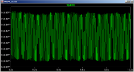
I've attached plots showing the pre-reg and post reg ripple from the sim.
1st plot is pre-reg with 4700 and 2200 uF caps. load is ~500mA at the output.
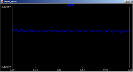
2nd plot is post-reg with 4700 and 2200 uF caps. load is ~500mA at the output.
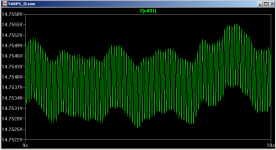
3rd plot is pre-reg with 10000uF and 4700uF caps load is ~500mv at the output.
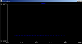
4th plot is post-reg with 10000uF and 4700uF caps load is ~500mv at the output.
Tony.
The values of the caps can be dropped to 4700uF for the first and 2200uF for the second ones with no noticeable degradation in the post regulator performance for the 200mA load... at a 500mA load the larger capacitors do make some difference (I had to drop the filter resistors to 2.2ohms to maintain enough voltage pre reg) The difference was 2uV ripple with the large caps compared to 8uV with the small. The voltage drop across the regulator was 4.5V increasing the voltage pre reg didn't seem to make any difference, but reducing it at all below 4.5V did make small differences (1uv and increasing for each .1V or so drop).
So having a volatge difference of at least 4.5V pre to post reg, and having as little ripple as possible pre reg seem to be key elements for achieving the cleanest output from the reg, at least in my simulated circuit anyway
I've attached plots showing the pre-reg and post reg ripple from the sim.
1st plot is pre-reg with 4700 and 2200 uF caps. load is ~500mA at the output.
2nd plot is post-reg with 4700 and 2200 uF caps. load is ~500mA at the output.
3rd plot is pre-reg with 10000uF and 4700uF caps load is ~500mv at the output.
4th plot is post-reg with 10000uF and 4700uF caps load is ~500mv at the output.
Tony.
Attachments
I chose the Linear Technology ones LT317A According to the datasheet they offer improved performance and are tighter tolerance. http://cds.linear.com/docs/Datasheet/lt0117.pdf
I paid $3.95 US for them.
Tony.
I paid $3.95 US for them.
Tony.
Use a big cap on the output (plus protection diode). Use a big cap on the adjust pin (ditto). Sink a lot of current (100mA or more). Bob Pease and Errol Dietz did some very detailed analysis on the effects of these caps and regulator current on noise and source impedance- worth hunting those papers up.
On the other hand, Texas Instruments, (which now owns National now) did a research piece in which they criticized over-damping the regulator.
- Status
- This old topic is closed. If you want to reopen this topic, contact a moderator using the "Report Post" button.
- Home
- Amplifiers
- Power Supplies
- LM317 cleanup