hi everyone
I bought the above amp ready built (schematic here HeadWize - Project: The 6N1P OTL Headphone Amplifier by Bruce Bender). it works fine but has a rather annoying hum that sounds like 50Hz. I'm asking here because I have zero experience with tubed gear and I know that they (tubes) have their specific problems.
Bruce mentions something about hum when the heater supply voltage.is not filtered but at a quick glance mine seems to have about 1800uF (4x470u) of capacitors on it.
any other places where I should investigate? thanks
Hum as you have it most probably comes from a grounding problem... but also depends on how the amp was built. Does it have the same psu like the one in the schematic?
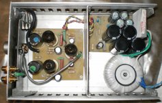
AC for the heaters should be no problem as long as the wires are tightly twisted and routed away from signal wiring... even with AC heaters the amp can be dead quiet. Can you post a picture of the internals?
you can also read about grounding here --> Star Grounding
AC for the heaters should be no problem as long as the wires are tightly twisted and routed away from signal wiring... even with AC heaters the amp can be dead quiet. Can you post a picture of the internals?
you can also read about grounding here --> Star Grounding
hi StixxHum as you have it most probably comes from a grounding problem... but also depends on how the amp was built. Does it have the same psu like the one in the schematic?
AC for the heaters should be no problem as long as the wires are tightly twisted and routed away from signal wiring... even with AC heaters the amp can be dead quiet. Can you post a picture of the internals?
you can also read about grounding here --> Star Grounding
and thanks for the quick reply. I have maybe average knowledge of electronics but when it comes to tubes I'm a complete noob. I know about grounding schemes and I'll check that too when I dismantle the thing completely. meanwhile, this is how it looks with the cover off (if that can reveal anything at all). will get back soon with more details.
Attachments
took a look at the way it's made and it's a bit different from Bruce's schematic. the differences can be seen in the attached pic (drawn in red).
other differences not seen in the pic:
- the power supply doesn't use the cap-res-cap-res-cap scheme, instead all caps are just wired in parallel
- one rail of the heater supply is shorted to ground
and star grounding is not thoroughly obeyed...
where should I start?
other differences not seen in the pic:
- the power supply doesn't use the cap-res-cap-res-cap scheme, instead all caps are just wired in parallel
- one rail of the heater supply is shorted to ground
and star grounding is not thoroughly obeyed...
where should I start?
Attachments
Changing R5 will have a significant impact on the bias point for V2. What's the reason for the change?
500 kOhm input pot is rather high impedance. I suggest lowering that to 47~100 kOhm at the most. If this is indeed the problem, you should be able to make the hum go away by turning the volume all the way down.
Does the hum change with the setting of the volume control at all?
I would probably prefer to leave the 100 Ohm and 1 MOhm on the input in place. Then I'd AC couple with a 220 nF cap between the volume pot and the junction at the top of R1. That way any DC from the source won't interfere with the biasing of V1.
If you have hum with the wiper of the pot grounded, I'd start looking for ground loops and implement star ground. Also make sure you take the output from the power supply from the last filter cap and not earlier.
~Tom
Hi Mr.Push_Pull,
Fom what I can see the amp is OK with the addition
of a plate as EMI barrier.The only thing that is not implemented is the
tying of the common return (ground) of the amp and power supply.
Read the starground article given and understand how an electrical
circuit works.
The point is both boards don't have a "common" ground and therefore
both pcbs are referencing their respective "ground" so there may be a difference in ground potential or voltage and get into the amp through
lowest ground resistance as it is relative dedending on trace or copper track
size and length.
So first connect both pcb ground,choose a suitable takeoff point from amp pcb to power supply pcb,now where you choose to connect at the power
supply can also be critical as different location may have higher noise.
Try the thick common return of the filter caps just before it feeds the amp pcb.Then if there is no hum,then choose a suitable chasis starground preferably near the raw AC power entry wires and then to earth ground pin of the AC power receptor.This is important as if there is a electrical fault the excess voltage will have somewhere to go and not through the appendages of your body and then the ground you are standing on.
Always think SAFETY FIRST.Discharge the high voltage caps to ground with a resistor of about 5 watt or bigger first! Measure the cap voltage to ensure all voltage is discharge.If you see
1 volt or less it is safe to dive in.
If there is hum still disconnect from chasis ground and work your way around until minimum hum and then connect to chasis ground.
Edit: It is obvious there is ground connection between both pcbs ( 1 pair of wires ) or else the amp will not work and if this is a diy thing observe the pcb trace below and see how it runs and you will get the picture.Are the heaters running on AC?I don't see any diode bridge or is it behind
the heatsink. If that is so then there would be some hum but it can be minimised.
Regards.
Last edited:
I have no idea. the guy who built it said it had some deviations from Bruce's schematic but couldn't tell exactly.Changing R5 will have a significant impact on the bias point for V2. What's the reason for the change?
nope. stays unchanged regardless.Does the hum change with the setting of the volume control at all?
it is both rectified and filtered. you're saying that rectifying it would cause hum?Are the heaters running on AC?I don't see any diode bridge or is it behind
the heatsink. If that is so then there would be some hum but it can be minimised.
all other points taken. I'll start troubleshooting as soon as I get home.
it's DIY.by seller he should QC before shipping??Regards.
it's DIY.
That explains it.Anyway this is a good way for you to learn and gain experience.
Regards.
sure, I could just leave it like that (the hum is not untolerable and I can't notice it while listening at decent levels) but I have the diseaseThat explains it.Anyway this is a good way for you to learn and gain experience.
Regards.
one more Q: do you think that omitting the 1K/500ohm resistors from the PS has its effect? I'm assumming Bruce didn't add them for no reason but OTOH 1800u sounds reasonable for a low load. which leads me to another question: what biasing class is this design?
I do a wild guess that the hum is caused by the build quality... not the circuit itself... metalwork looks rather crude.
Changing R5 means the the output tubes draw a lot less current... probably only 3mA instaed of 10mA... which is rather strange because now the output tubes draw less current than the input? (I built the MJ variation of this amplifier...)
Are the RCA inputs isolated from the chassis...? I can't see any isolating washers...
one more Q: do you think that omitting the 1K/500ohm resistors from the PS has its effect?
Don't understand that one
no, they're not isolated. that's a good point, I totally missed that.I do a wild guess that the hum is caused by the build quality... not the circuit itself... metalwork looks rather crude.
Changing R5 means the the output tubes draw a lot less current... probably only 3mA instaed of 10mA... which is rather strange because now the output tubes draw less current than the input? (I built the MJ variation of this amplifier...)
Are the RCA inputs isolated from the chassis...? I can't see any isolating washers...
I'll switch to original part values too.
the original PS has a parallel cap / series resistor / parallel cap / series R / parallel C topology. the implementation I own omits the series resistors. how critical are those resistors?Don't understand that one
Don't understand that one
No you can't remove R5 as it is the biasing resistor and if original is 220 ohm
I think the designer has good reason.Can MJ be the japanese magazine?
IF so the japanese like to bias with low current for long life of tube and to them may sound better?But if you bias at now 1K like Stixx said at 10mA
then you are running it hot so don't expect to last long but if you like the way it sounds at high current so be it.
regards.
Edit: So now the bias is 3mA? That's up to you,but I think you would want more current?.If you omit the series resistors of the power supply as they form a RC filter for ripple then you just have capacitor filtering and not a pi filter but if you do follow the original then I'm afraid your B+ will change and you will have to readjust the anode voltage.
Last edited:
I'm talking about the 1k/2W resistors in the power supply. I understand that R5 is a biasing resistor (the parallel cap would indicate that) and can't be omitted.
PS: what japanese magazine are you referring to? MJ stands for Morgan Jones if I understand correctly
PS: what japanese magazine are you referring to? MJ stands for Morgan Jones if I understand correctly
Attachments
Absolutely correct... Morgan J. did the original schematic as published on Headwize.MJ stands for Morgan Jones if I understand correctly
Also correct: R5 has to stay in the circuit or nothing will work
When the builder left out the series resistors in the psu (????) this is a strange one... because then he changed the topology from CRCRC to C only... which would mean much worse filtering of ripple.
Btw. you can easiliy simulate psu topologies in PSUD2 (free download) to get some insight... maybe the builder left out the R's since he didn't have enough voltage to start with? You definitely need at least one R in your filter... like CRC.
I'm talking about the 1k/2W resistors in the power supply. I understand that R5 is a biasing resistor (the parallel cap would indicate that) and can't be omitted.
PS: what japanese magazine are you referring to? MJ stands for Morgan Jones if I understand correctly
Ahh.... that's the voltage droping resistors to get 348V but if your circuit is not using 348V and something lower and most important your AC secondary
is not giving 250Vac then of course your value of resistor is different so
you base it on your transformer and circuit design, not the drawing.
regards.
MJ is the famous japanese audio magazine. but it seems I am mistaken.
oh, I get it. the original designer had only that Hammond transformer at hand and used the resistors just for dropping the voltage.Ahh.... that's the voltage droping resistors to get 348V but if your circuit is not using 348V and something lower and most important your AC secondary
is not giving 250Vac then of course your value of resistor is different so
you base it on your transformer and circuit design, not the drawing.
regards.
MJ is the famous japanese audio magazine. but it seems I am mistaken.
PS: I've been avoiding to call it a PI filter as AFAIK the nomenclature refers strictly to the case when a series inductor is used
Last edited:
- Status
- This old topic is closed. If you want to reopen this topic, contact a moderator using the "Report Post" button.
- Home
- Amplifiers
- Tubes / Valves
- Headwize 6N1P OTL headphone amp having hum