I was looking at a schematic the other day where the preamp valve section of an amp was grounded cathode but instead of the grid leak resistor connecting from grid to ground it was connected between the two cathode resistor bias network which was formed by two resistors in series (thus making a divider).
Now obviously this reduces gain and provides even more cathode feedback but the designer/modder claimed it was sonically very crucial for reducing distortion etc.
I have not seen this many times at all and I cannot find reference to this technique in the usual texts/sites.
Can someone analyze this a little bit and the various pros and cons involved?
What you are decribing is known as a bootstrap circuit. Bootstraping is an arrangement of components used to boost the input impedance of a circuit by using a small amount of positive feedback. This type of input circuit is typically only used when someone wants to raise the input impedance of an amplifier to prevent loading of a sensitive privous source. This circuit topology is rarely used as it induces positive feedback. Thus, bootstrapped circuits usually suffer from poorer stability and noise performance compared to ones that don't bootstrap. Mickeystan
Theory= Morgan Jones Valve amps 4th ed (p.102)....Radiotron Hbk 4th ed; ch 7 (p.322)
Mickeystan.......I use this topology 100%......when used correctly even with high gm video tubes not only does it raise the input Z, but also an excellent linearising method in driver stages with mismatched tubes.
richy
Mickeystan.......I use this topology 100%......when used correctly even with high gm video tubes not only does it raise the input Z, but also an excellent linearising method in driver stages with mismatched tubes.
richy
I was looking at a schematic the other day where the preamp valve section of an amp was grounded cathode but instead of the grid leak resistor connecting from grid to ground it was connected between the two cathode resistor bias network which was formed by two resistors in series (thus making a divider).
I guess you mean something like this (attached). It's frequently done when you need a higher than normal tail voltage. Vgk sees the normal grid bias, but the cathode is much farther above DC ground than what would be considered the normal bias voltage.
You can do the same thing with LTPs in order to increase the length of the tail, either by running the cathode at an elevated positive voltage, or connecting the far end of the tail to a negative DC rail.
Another place you frequently see it is with AC coupled cathodyne phase splitters.
Attachments
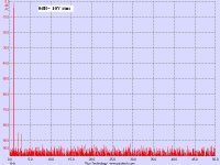
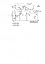
From my 1950's scratch pad, this is the building block I get excellent results from. A combination of positive & negative feedback and this cirucit offers excellent transient response. Not optimised in terms of noise, but harmonics with 10V rms o/p already very low and below -90dB signal source harmonics begin to come though as with sampling bit errors. As with triodes, deducing thd at lower levels is simply a divisor. Normally the pot is a preset.
Commercial variations of this circuit were about in the early 1960's, variations of the technique used by Brimar and others created an equalizer out of the 2nd anode feedback to 1st stage cathode, but doing further tests I found the RIAA and Tape head EQ not optimised in terms of noise but alignment followed the curves. Proper analysis is required as in those days, anything which quoted a noise figure of -60dB for the RIAA for the platter & tape was deemed good enough.
richy
Attachments
What I saw was a simple grounded cathode preamp driver stage , plate loaded.
However no global feedback was applied from the succeeding stages.
Now assuming that you are not interested in high input z since it is the first or second driver stage of a SET amp what would bootstrapping accomplish in this case?
If I understand it correctly positive feedback will increase gain, right?
Also why would one want a higher tail voltage?
Had a look at my Morgan Jones p.102. Thanks for the info.
However bootstrapping is used there for a cathode follower in order to overcome the problem of low input z when using fixed bias arrangement from plate to grid to ground.
It is not done with the common cathode amplifier with the output at the plate which is what I am referring to.
However bootstrapping is used there for a cathode follower in order to overcome the problem of low input z when using fixed bias arrangement from plate to grid to ground.
It is not done with the common cathode amplifier with the output at the plate which is what I am referring to.
This is the circuit I am referring to. What do you think?
http://www.lampizator.eu/AMPLIFIERS/CHINA/845/new circuit from austria/ma845_v42.pdf
http://www.lampizator.eu/AMPLIFIERS/CHINA/845/new circuit from austria/ma845_v42.pdf
- Status
- This old topic is closed. If you want to reopen this topic, contact a moderator using the "Report Post" button.
- Home
- Amplifiers
- Tubes / Valves
- current/cathode feedback