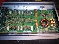
It is a 4 channel amp 720W max. When I try to switch it on, it stays in protection mode for 5 seconds. I guess it is normal because I have another Magnat amp which is in good working order, it stays also in protection mode for 5 seconds and then switches on. But with this one, as soon as the protection LED goes out and power LED on, it makes my power supply switch off as if there was a short circuit. My power supply can handle up to 16 A of current, I think my amp is just drawing more and thats why power supply switches off.
All the output transistors are OK, board looks good, no burn marks...
Only thing that was strange to me, was the biggest diode on the board, right next to B+, remote and ground terminals. I set my multimeter to diode test (2k ohm resistance), I checked the smaller diodes near power terminals, and these were OK as far as I understand checking diodes: + wire on anode, - wire on cathode - 1.1k ohm resistance, + wire on cathode, - wire on anode - more resistance than multimeter can display.
Checked the big diode the same way as well but that was more like measuring resistance on capacitor, slowly growing no matter which way the test wires were. I did not solder components out. Has the big diode failed or am I checking them incorrectly? If it has failed then why?
Attachments
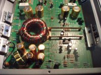
If it only trips the supply after remote voltage is applied (not with the B+ and ground connected) and there are no solder bridges on the rectifier pads, you may have a shorted transformer. It's also possible that the driver IC is defective. To eliminate it as the faulty component, remove the power supply FETs and measure the DC voltage on pins 9 and 10 of the IC. They should have ~5v DC.
Supply trips even without remote connected. Rectifier pads I checked with multimeter, no continuity between pads. While removing the FETs I discovered that one of them is shorted, dont know how I missed that earlier. Removed all of them and now I am going to check voltage on IC pins.
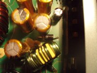
There are symbols on the board and on the rectifiers. I matched them, so I think I got them right.
Rectifiers are checked like diodes, yes? If so then they check out OK. + wire on anode, - on cathode, multimeter set to diode check (2k ohm resistance) I get .844 ohm resistance between legs 1-2 2-3 on both rectifiers. Chenge the wires the other way I get more resistance than the multimeter can display.
One looks like it has been replaced before, It has longer legs and when installed, it does not look like its from factory. All the other transistors are aligned but this one sticks up higher. Is it possible that someone replaced the original rectifiers with wrong ones? I have FMU22S and FMU22R, they sound right for this amp? I requested schematics from Magnat but havent heard from them yet.
If rectifiers are OK what could be wrong then? Maybe my supply is just too weak for this amp?
- Status
- This old topic is closed. If you want to reopen this topic, contact a moderator using the "Report Post" button.
- Home
- General Interest
- Car Audio
- Magnat Crusader 720 failing to switch on