better you try this one ...
probably more versatile as opposed to single ended...
E
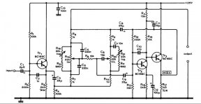
The WW schematic is OK, provided you realise that noise levels will be high, relative to modern designs, as there is no indication or provision of regulation, filtering of the power rail or suggestions for what to do about RFI or EMI if they become a problem in your board layout and wiring.
You will be on your own unless it is detailed in an article there, possibly relying on lots of bypassing, filtering and careful grounding. Personally, I would shield this or keep it separate in a freestanding preamp. The adjustment of R18,21 seems quite a strange feature. Is the setting explained in the text?
You will be on your own unless it is detailed in an article there, possibly relying on lots of bypassing, filtering and careful grounding. Personally, I would shield this or keep it separate in a freestanding preamp. The adjustment of R18,21 seems quite a strange feature. Is the setting explained in the text?
about line regulation i am planning to use a shunt regulator.About RFI or EMI , would a 47pf cap across base -collector of first emmiter follower transistor be helpful?
this is the article . http://www.keith-snook.info/wireles...1974/Baxandall tone control revisited DCD.pdf
this is the article . http://www.keith-snook.info/wireles...1974/Baxandall tone control revisited DCD.pdf
Last edited:
I remember a very similar circuit in Practical Wireless, probably around 1976 ? It looked very similar from memory but just had the two conventional pots.
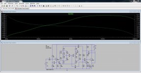
Anyhow... I couldn't resist seeing how this worked in simulation. Its very much of its time, probably sounds "nice" but ultimately lacks the precision that opamps bring to the response. The response here is with the pots centred, looks awful, but look at the scale. Perhaps not so bad in context.
Anyhow... I couldn't resist seeing how this worked in simulation. Its very much of its time, probably sounds "nice" but ultimately lacks the precision that opamps bring to the response. The response here is with the pots centred, looks awful, but look at the scale. Perhaps not so bad in context.
Attachments
") I see you have reworked a lot of the values.
I see you have reworked a lot of the values.no i havent reworked anything yet. the only thing i did was to add 0.47u bypass capacitors to all electrolytic caps that pass signal,added base collector capacitor to first transistors,added rail bypass capacitors and 100ohm resistor at output. the writer used 25V supply rail and a boost cut of +-18db. i will have to recalculate values for +-10db boost/cut and maybe i use 30V for supply rail.
which WW article are we looking at for reference...
Regards,El
The original article is by M V Thomas and is available on line at http://www.keith-snook.info/wireless-world-magazine/Wireless-World-1974/Baxandall%20tone%20control%20revisited%20DCD.pdf
--gannaji
Sorry, my mistake, the ref to original article is already given!
Last edited:
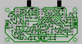
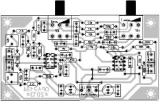
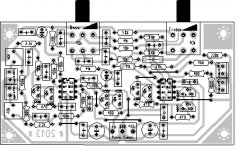
Mooly , i also made 2 pcb layouts for 2 band tone control using opamps this time. both pcbs include input filter,but the main difference is that the one pcb includes fets for class A biasing of opamps and the other one not. which version do you think is better to etch?
Attachments
- Status
- This old topic is closed. If you want to reopen this topic, contact a moderator using the "Report Post" button.
- Home
- Amplifiers
- Solid State
- 2 band transistor tone control